Pump body assembly, fluid machine and heat exchange equipment

A component and pump body technology, which is applied in the direction of mechanical equipment, pump components, liquid fuel engines, etc., can solve the problems of easy eccentric rotation of the piston sleeve and affect the working efficiency of the pump body components, etc., and achieve the goal of improving operation reliability and performance Effect

Pending Publication Date: 2018-11-13
GREE ELECTRIC APPLIANCES INC
View PDF4 Cites 2 Cited by
  • Summary
  • Abstract
  • Description
  • Claims
  • Application Information

AI Technical Summary

Problems solved by technology

[0003] The main purpose of the present invention is to provide a pump body assembly, fluid machinery and heat exchange equipment to solve the problem in the prior art that the piston sleeve of the pump body assembly is prone to eccentric rotation and affects the working efficiency of the pump body assembly

Method used


Image

  • Pump body assembly, fluid machine and heat exchange equipment
  • Pump body assembly, fluid machine and heat exchange equipment
  • Pump body assembly, fluid machine and heat exchange equipment

Examples


Embodiment 1

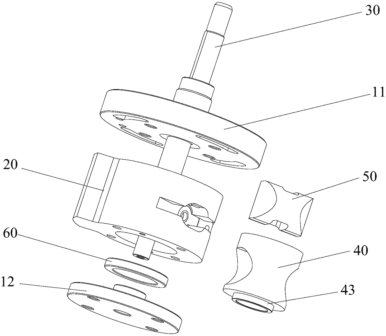
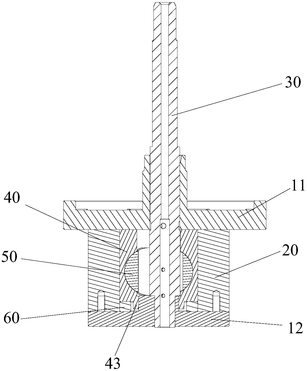
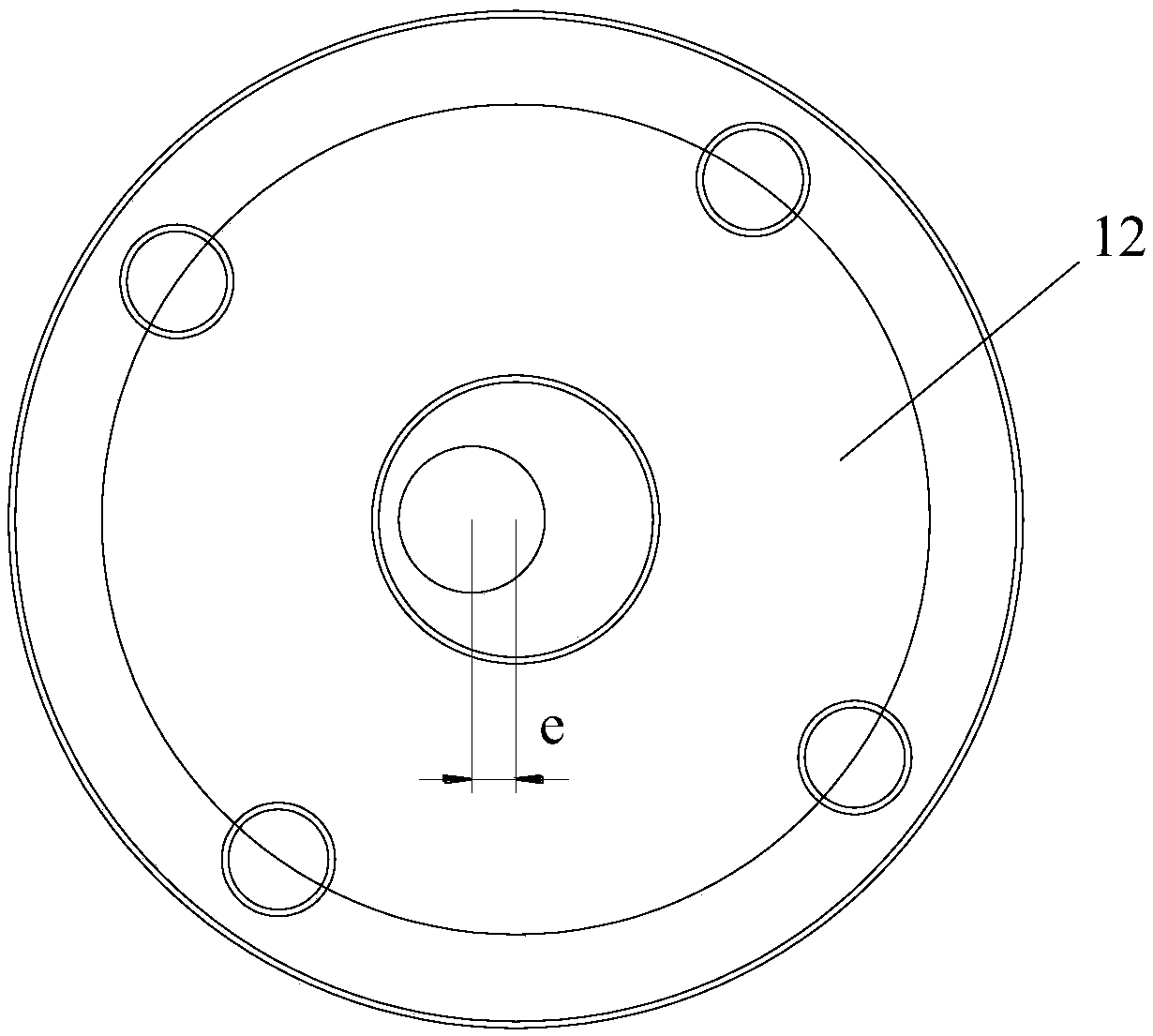
[0071] Such as Figure 1 to Figure 3 As shown, the pump body assembly includes a lower flange 12, a lower wear reducing ring 60, a cylinder 20 and a piston assembly. Wherein, the lower wear reducing ring 60 is located in the cylinder 20 , and the lower flange 12 is located below the cylinder 20 . The piston assembly is arranged in the cylinder 20. The piston assembly includes a piston sleeve 40 and a piston 50 slidably arranged in the piston sleeve 40. The lower end surface of the piston sleeve 40 and the lower wear-reducing ring 60 are limitedly fitted to prevent the piston sleeve 40 from facing each other. Displacement in the radial direction occurs at the lower flange 12 .

[0072] Applying the technical solution of this embodiment, during the operation of the pump body assembly, the lower anti-friction ring 60 acts as a limit stop on the lower end of the piston sleeve 40, thereby preventing the piston sleeve 40 from moving in the radial direction during operation. Ensuri...

Embodiment 2

[0081] The difference between the pump body assembly in the second embodiment and the first embodiment is that the structure of the lower wear-reducing ring 60 is different.

[0082] Such as Figure 4 to Figure 8 As shown, the surface of the piston sleeve 40 facing the lower wear-reducing ring 60 has a limiting protrusion 43, and the surface of the lower wear-reducing ring 60 facing the piston sleeve 40 has a seventh limiting groove 61, and the limiting protrusion 43 extends into The seventh limiting groove 61 is in and stops with the seventh limiting groove 61 . Specifically, during the operation of the pump body assembly, the stop protrusion 43 of the piston sleeve 40 extends into the seventh stop groove 61 of the lower wear-reducing ring 60, and the surface of the stop protrusion 43 and the seventh stop The limit stopper of the groove wall of the groove 61 is used to realize the limit and support of the lower wear-reducing ring 60 to the radial direction of the piston slee...

Embodiment 3

[0085] The difference between the pump body assembly in the third embodiment and the first embodiment is that the structure of the lower wear-reducing ring 60 is different.

[0086] Such as Figure 9 to Figure 12 As shown, the surface of the lower antifriction ring 60 facing the piston sleeve 40 has a fifth extension portion 62 , the fifth extension portion 62 protrudes into the piston sleeve 40 and makes a limit stop with the inner surface of the piston sleeve 40 . Specifically, the fifth extension portion 62 extends into the lower end of the piston sleeve 40 and cooperates with the inner surface of the piston sleeve 40 so as to realize the radial limit of the piston sleeve 40 by the lower wear-reducing ring 60 and prevent the piston sleeve 40 from moving in the radial direction. Shift in the direction to realize the limit and support of the upper end of the piston sleeve 40 by the lower wear-reducing ring 60, prevent the piston sleeve 40 from eccentric and tilted rotation, e...


PUM


Abstract

The invention provides a pump body assembly, a fluid machine and heat exchange equipment. The pump body assembly comprises a lower flange, a lower wearing ring, an air cylinder and a piston assembly,wherein the lower wearing ring is positioned in the air cylinder, and the lower flange is positioned below the air cylinder; the piston assembly is arranged in the air cylinder and comprises a pistonsleeve and a piston slidably disposed within the piston sleeve, and the lower end face of the piston sleeve is in limiting fit with the lower wearing ring to prevent radial displacement of the pistonsleeve relative to the lower flange. The pump body assembly effectively solves the problem that a piston sleeve of a pump body assembly in the prior art is prone to generate eccentric rotation and affects the working efficiency of the pump body assembly.

Description

technical field [0001] The invention relates to the technical field of pump body components, in particular to a pump body component, fluid machinery and heat exchange equipment. Background technique [0002] At present, during the operation of the pump body assembly, the piston sleeve is prone to eccentricity and tilt rotation, which causes the piston sleeve to easily rub against the cylinder and the piston, seriously affecting the working efficiency and performance of the pump body assembly. Contents of the invention [0003] The main purpose of the present invention is to provide a pump body assembly, fluid machinery and heat exchange equipment to solve the problem in the prior art that the piston sleeve of the pump body assembly is prone to eccentric rotation and affects the working efficiency of the pump body assembly. [0004] In order to achieve the above object, according to one aspect of the present invention, a pump body assembly is provided, including: a lower fl...

Claims


Application Information

Patent Timeline
Patent Type & Authority Applications(China)
IPC IPC(8): F04C18/00F04C29/00
CPCF04C18/00F04C29/00F04C2240/80F04C2240/20F04C2240/10F04C2240/60
Inventor 杜忠诚任丽萍梁社兵李直杨森张荣婷史正良郭霜许甲岿尚文海
Owner GREE ELECTRIC APPLIANCES INC
Why Eureka
Try Eureka