MASSIVE MIMO antenna

An antenna and channel technology, applied in the field of MASSIVE MIMO antennas, can solve the problems of large antenna volume, achieve high miniaturization, optimize electrical parameter matching performance, and realize the effect of miniaturization

Active Publication Date: 2018-11-13
COMBA TELECOM TECH (GUANGZHOU) CO LTD
View PDF12 Cites 15 Cited by
  • Summary
  • Abstract
  • Description
  • Claims
  • Application Information

AI Technical Summary

Problems solved by technology

[0004] Based on this, it is necessary to provide a MASSIVE MIMO antenna with a high degree of miniaturization to solve the problem of large volume of existing base station antennas

Method used


Image

  • MASSIVE MIMO antenna
  • MASSIVE MIMO antenna
  • MASSIVE MIMO antenna

Examples


Embodiment Construction

[0026] In order to facilitate the understanding of the present invention, the present invention will be described more fully below with reference to the associated drawings. Preferred embodiments of the invention are shown in the accompanying drawings. However, the present invention can be embodied in many different forms and is not limited to the embodiments described herein. On the contrary, these embodiments are provided to make the understanding of the disclosure of the present invention more thorough and comprehensive.

[0027] It should be noted that when an element is referred to as being “fixed” to another element, it can be directly on the other element or there can also be an intervening element. When an element is referred to as being "connected to" another element, it can be directly connected to the other element or intervening elements may also be present. The terms "vertical," "horizontal," "left," "right," and similar expressions are used herein for purposes ...


PUM


Abstract

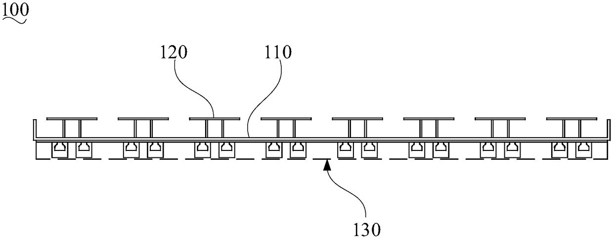
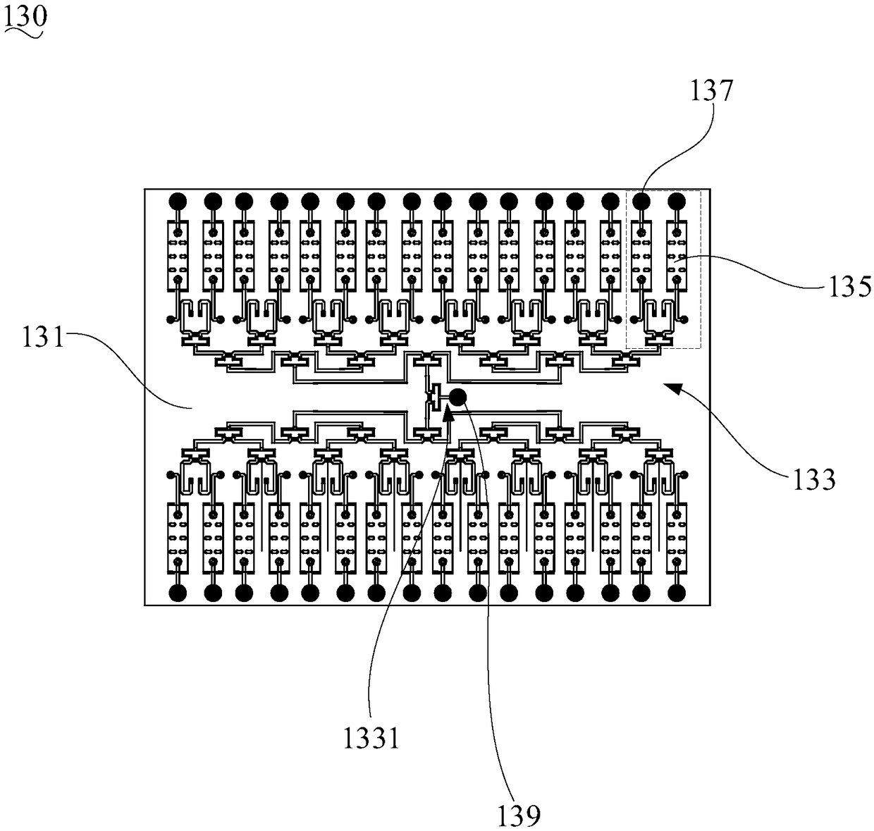
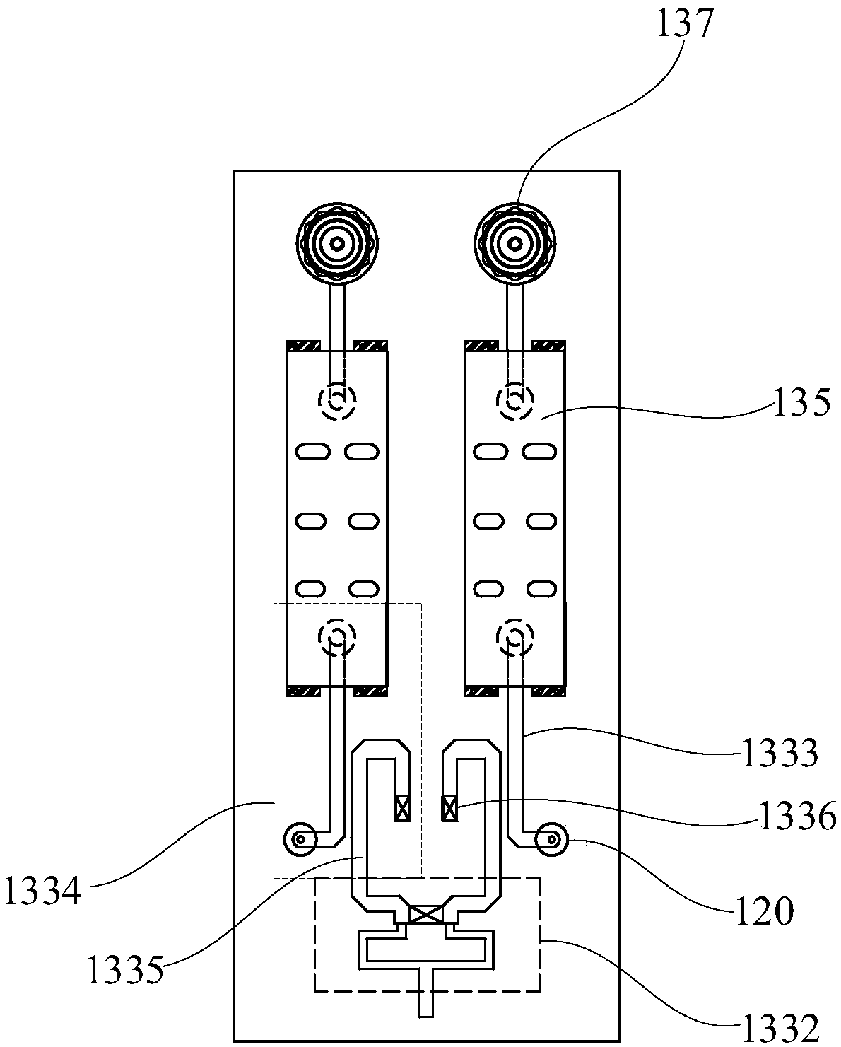
The invention relates to a MASSIVE MIMO antenna. The MASSIVE MIMO antenna comprises a reflecting plate, a plurality of radiating units and a calibration module, wherein a calibration network, filtersand RF connectors are integrated on a PCB of the calibration module, so that the calibration module has the functions of signal calibration and filtering simultaneously, and an external filter is notneeded in the use process of the MASSIVE MIMO antenna. Moreover, the calibration network, the filters and the RF connectors are integrated by the PCB, and the structure of the calibration module is more compact. Therefore, the MASSIVE MIMO antenna has a higher degree of miniaturization, and a communication base station is miniaturized. Besides, due to integral design of the filters and the calibration module, matching performance of electrical parameters of the two cascaded components can be fully considered in design and can be optimized as much as possible, and accordingly, optimal interconnection design between the filter performance and the antenna performance is achieved.

Description

technical field [0001] The invention relates to the technical field of wireless communication, in particular to a MASSIVE MIMO antenna. Background technique [0002] Mobile communications are evolving from 4G to 5G, and MASSIVE MIMO (Massive Multiple Input Multiple Output) antennas are widely used. In a traditional massive MIMO antenna, a cavity filter is usually installed on the back of the antenna. The input port of the filter is connected to the signal receiving / transmitting circuit module of the base station equipment, and the output port is connected to the antenna port. [0003] With the development of mobile communication and the deepening of network coverage, site resources are becoming more and more tight, so higher requirements are put forward for the miniaturization and light weight of base station equipment. However, in the existing base station antenna, since the same number of external filters as the number of antenna ports needs to be installed, the volume of...

Claims


Application Information

Patent Timeline
Patent Type & Authority Applications(China)
IPC IPC(8): H01Q1/36H01Q1/38H01Q1/50H01Q23/00
CPCH01Q1/36H01Q1/38H01Q1/50H01Q23/00
Inventor 刘培涛陈礼涛李明超赖展军黄明达李轶帆苏国生段红彬丁海范颂东
Owner COMBA TELECOM TECH (GUANGZHOU) CO LTD
Why Eureka
Try Eureka