A rotor structure with split pressing plate

A rotor structure, split technology, applied in the magnetic circuit shape/style/structure, magnetic circuit rotating parts and other directions, can solve the problems of poor axial ventilation of the magnetic pole module, potential safety hazards, rework, etc., to reduce the frequency of rework, improve Work efficiency and the effect of eliminating safety hazards

Active Publication Date: 2021-03-26
CRRC YONGJI ELECTRIC CO LTD
View PDF3 Cites 0 Cited by
  • Summary
  • Abstract
  • Description
  • Claims
  • Application Information

AI Technical Summary

Problems solved by technology

[0003] The present invention aims to solve the technical problems of potential safety hazards, rework, and poor axial ventilation of the magnetic pole modules caused by failure to compress each existing magnetic pole module in time

Method used


Image

  • A rotor structure with split pressing plate
  • A rotor structure with split pressing plate
  • A rotor structure with split pressing plate

Examples


Embodiment Construction

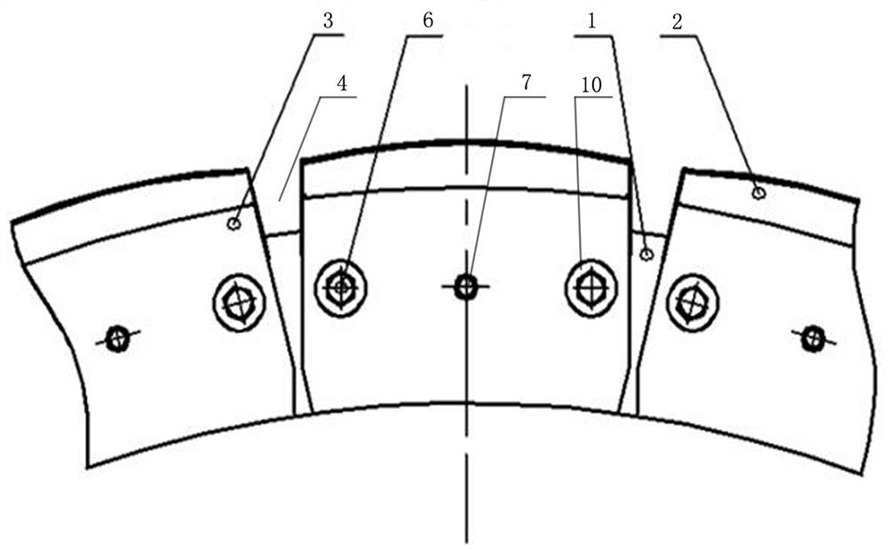
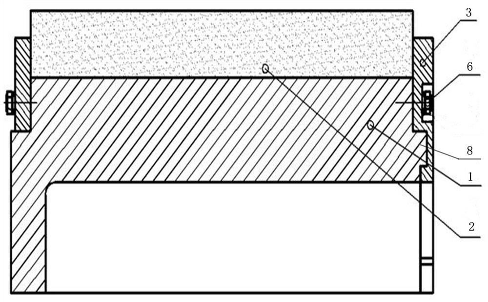
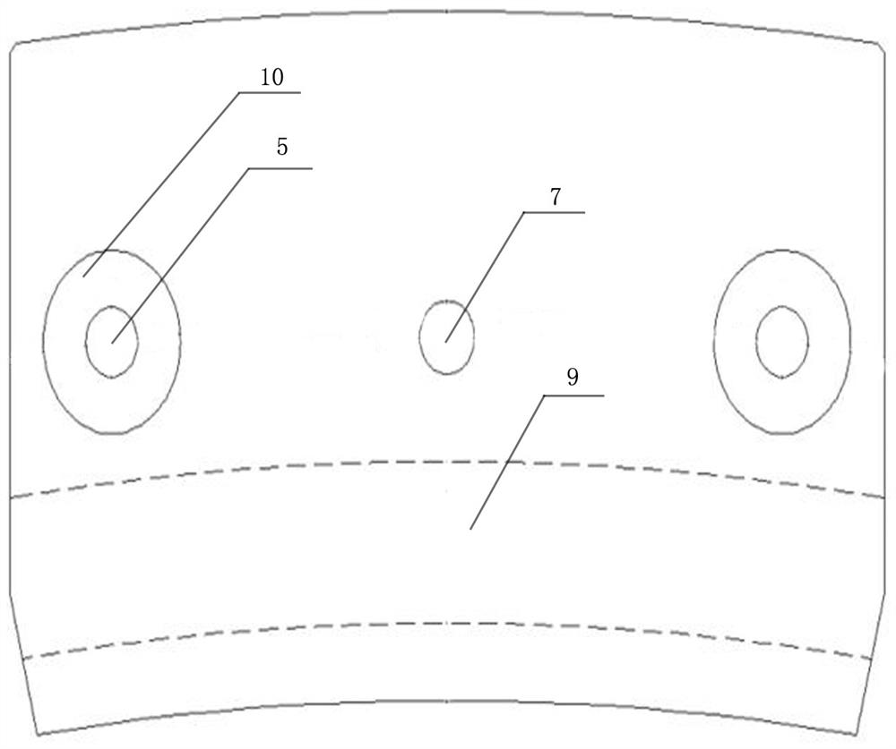
[0012] refer to Figure 1 to Figure 4 , a rotor structure with a split pressure plate in the present invention, including a rotor yoke 1, a plurality of split magnetic pole modules 2 are evenly distributed on the outer circumference of the rotor yoke 1, and the axial ends of the rotor yoke 1 are provided with Press the pressure plate of the magnetic pole module 2, and the pressure plate at least one end of the rotor yoke 1 is set as a split type pressure plate (the "at least" here includes two technical solutions: one is that both ends of the rotor yoke 1 are set as split. One-piece pressure plate, the other is that one end of the rotor yoke 1 is set as a split type pressure plate, and the other end adopts an existing integrated pressure plate), the split type pressure plate is composed of several concentric and equal-diameter fan rings or deformed fan ring baffles 3 components ("concentric" means the center of the circle is the same, "equal diameter" means that the inner diam...


PUM


Abstract

The invention discloses a rotor structure with a split type pressing plate, and relates to the field of motor accessories, in particular to the rotor structure with the split type pressing plate; according to the technical scheme, the rotor structure comprises a rotor magnet yoke, wherein a plurality of magnetic pole modules which are arranged in a split mode are uniformly distributed on the outercircumference of the rotor magnet yoke, and pressing plates used for tightly pressing the magnetic pole modules are arranged at the two ends of the axial direction of the rotor magnet yoke; the rotorstructure is characterized in that the pressing plate on at least one end of the rotor magnet yoke is arranged as a split type pressing plate, and the split type pressing plate is composed of a plurality of deformation fan-shaped baffles with concentric modes and equal diameters, and the baffles are arranged corresponding to the magnetic pole modules; a ventilation gap is formed between every twoadjacent baffles, and at least two bolt holes are formed in each baffle; bolts for fixing the baffles and the rotor magnet yoke are inserted into the bolt holes; and mounting holes corresponding to the bolt holes are formed in the end plane of the rotor magnet yoke. The rotor structure is mainly used for assembling a rotor of a motor, in particular to a rotor assembly of a semi-direct drive permanent magnet wind driven generator.

Description

technical field [0001] The invention relates to the field of motor accessories, in particular to a rotor structure with split pressure plates. Background technique [0002] The rotor structure of the semi-direct drive permanent magnet wind turbine usually consists of a rotor yoke, magnetic pole modules distributed uniformly in the circumferential direction outside the rotor yoke, and pressure plates located at both ends of the rotor yoke. The existing pressure plates all adopt an integrated structure. During assembly, the rotor pressure plate on one side is installed first, then the magnetic pole modules are installed separately, and finally the rotor pressure plate on the other side is installed. This structure and installation method, on the one hand, after the installation of each magnetic pole module, if it is not pressed in time, it is easy for the magnetic steel to jump out or loosen, which has certain potential safety hazards, and it is easy to cause rework and reduce...

Claims


Application Information

Patent Timeline
Patent Type & Authority Patents(China)
IPC IPC(8): H02K1/27H02K1/32
CPCH02K1/27H02K1/32
Inventor 俞文斌尤佰朋李新奇王晓明
Owner CRRC YONGJI ELECTRIC CO LTD
Why Eureka
Try Eureka