Eureka AIR delivers breakthrough ideas for toughest innovation challenges, trusted by R&D personnel around the world.

A frequency scanning method and device for a small-bandwidth communication system

A communication system and frequency scanning technology, applied in wireless communication, access restrictions, electrical components, etc., can solve problems such as affecting search efficiency, and achieve the effect of improving efficiency and shortening sampling waiting time.

Active Publication Date: 2021-01-26
SANECHIPS TECH CO LTD
View PDF7 Cites 0 Cited by
  • Summary
  • Abstract
  • Description
  • Claims
  • Application Information

AI Technical Summary

Problems solved by technology

If the traditional method of correlation calculation for synchronous signals is used, firstly perform a rough scan of the entire frequency band, and then perform a fine scan and search for the frequency band after the rough scan, at least 20ms of sampling time is required for the correlation calculation of each frequency point, so it is necessary It takes a longer time to scan all the frequency points completely, which will affect the subsequent search efficiency
Moreover, this frequency scanning method will also bring a lot of challenges to the power consumption of NB-ioT terminals
[0005] Existing frequency scanning methods are mainly applicable to communication systems with relatively large and variable system bandwidths such as LTE, and frequency scanning patents rarely mention fast frequency scanning in small bandwidth communication systems such as NB-ioT method

Method used


Image

  • A frequency scanning method and device for a small-bandwidth communication system
  • A frequency scanning method and device for a small-bandwidth communication system
  • A frequency scanning method and device for a small-bandwidth communication system

Examples


Embodiment Construction

[0047] The preferred embodiments of the present invention will be described below in conjunction with the accompanying drawings. It should be understood that the preferred embodiments described here are only used to illustrate and explain the present invention, and are not intended to limit the present invention.

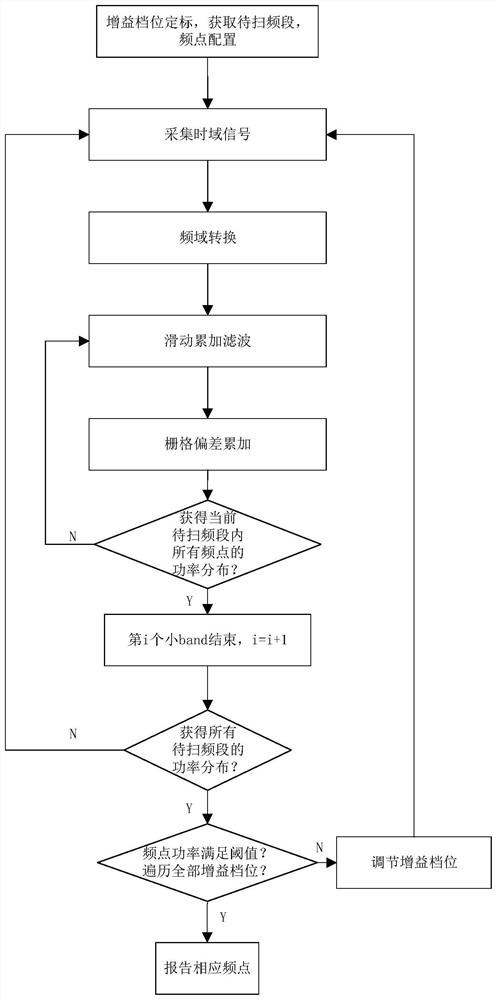
[0048] refer to figure 1 The flow chart of the frequency scanning method for the small bandwidth communication system provided by this embodiment includes the following steps:

[0049] Step 1, gain gear calibration, obtain the frequency band to be scanned, and configure frequency points;

[0050] Step 2, collecting time-domain signals according to the gain gear and the selected frequency requirements of the frequency band to be scanned;

[0051] Step 3, converting the collected time-domain signal into a frequency-domain signal;

[0052] Step 4, performing sliding accumulation filtering on the signal;

[0053] Step 5, performing a grid deviation accumulation opera...


PUM


Abstract

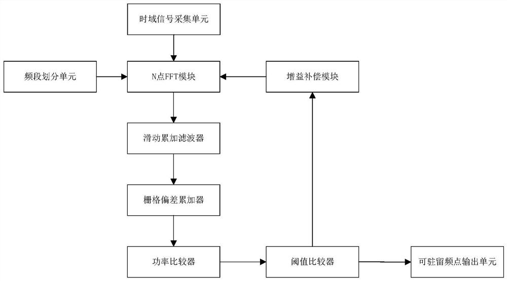
The invention discloses a frequency sweeping method and device for a small bandwidth communication system. A to-be-swept band is divided into a plurality of subbands according to system performance; frequency points in each subband are determined according to the minimum bandwidth of a system; FFT operation, slide accumulation operation and grid deviation accumulation operation are carried out ontime domain signals according to fixed gain; and after power distribution of all frequency points on the to-be-swept band are obtained, whether to adjust gain values to recalculate the power of each frequency point is decided according to a threshold demand. All frequency points of which power satisfying the threshold demand are screened according to the method, namely, all resident frequency points are obtained. According to the method and the device, the collected time domain signals are processed according to the fixed gain; the AGC (Automatic Gain Compensative) convergence time does not need to be reserved; and the integrated data processing time is greatly reduced. According to the method and the device, the frequency point distribution in each subband is determined according to the minimum bandwidth of the system and the power of each real frequency point is directly calculated in an bandwidth mode, so the sweeping omission condition resulting from the fact that calculated central frequency points are not the real frequency points is avoided.

Description

technical field [0001] The invention relates to the field of wireless communication, in particular to a frequency scanning method and a device thereof for a small-bandwidth communication system. Background technique [0002] After the current mobile communication terminal is turned on, if there are historical frequency points stored in the terminal, it will usually try to camp on the historical frequency points first. If the camping attempt fails, or the terminal itself does not store historical frequency points, it needs to perform frequency scanning in all possible frequency bands to find a frequency point that can access the network. Scanning of frequency points is also unavoidable when the mobile terminal needs to re-detect and select a PLMN. [0003] In the traditional frequency scanning method, a rough scan is first performed on all possible frequency points in a given frequency band by performing correlation calculation on the synchronous signal. During rough scanni...

Claims


Application Information

Patent Timeline
Patent Type & Authority Patents(China)
IPC IPC(8): H04W48/16H04W24/08H04W24/02
CPCH04W24/02H04W24/08H04W48/16
Inventor 赵青萍甘前超
Owner SANECHIPS TECH CO LTD
Why Eureka
Eureka Blog
Learn More