
Beam failure recovery processing method, terminal and network side device

A network-side device and recovery processing technology, applied in electrical components, wireless communication, etc., can solve problems such as large link recovery delay, high-level wireless link connection failure, etc., and achieve the effect of reducing recovery delay

Active Publication Date: 2018-11-13
VIVO MOBILE COMM CO LTD
View PDF3 Cites 16 Cited by
  • Summary
  • Abstract
  • Description
  • Claims
  • Application Information

AI Technical Summary

Problems solved by technology

However, if there is no suitable candidate beam when the beam failure recovery mechanism is activated, it may trigger a high-level wireless link connection failure, resulting in a large link recovery delay

Method used


Image

  • Beam failure recovery processing method, terminal and network side device
  • Beam failure recovery processing method, terminal and network side device
  • Beam failure recovery processing method, terminal and network side device

Examples


Embodiment Construction

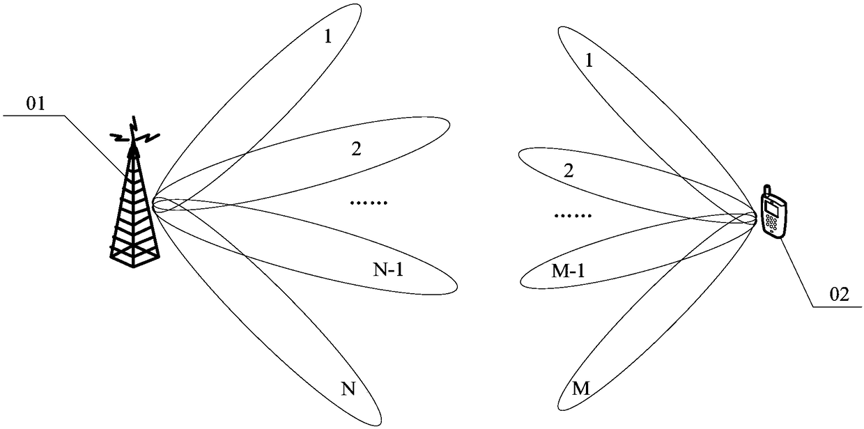
[0047] Reference will now be made in detail to the exemplary embodiments, examples of which are illustrated in the accompanying drawings. When the following description refers to the accompanying drawings, the same numerals in different drawings refer to the same or similar elements unless otherwise indicated. The implementations described in the following exemplary embodiments do not represent all implementations consistent with this application. Rather, they are merely examples of apparatuses and methods consistent with aspects of the present application as recited in the appended claims.

[0048] The terms "first", "second" and the like in the specification and claims of the present application are used to distinguish similar objects, and are not necessarily used to describe a specific order or sequence. It is to be understood that the data so used are interchangeable under appropriate circumstances such that the embodiments of the application described herein, for example...


PUM


Abstract

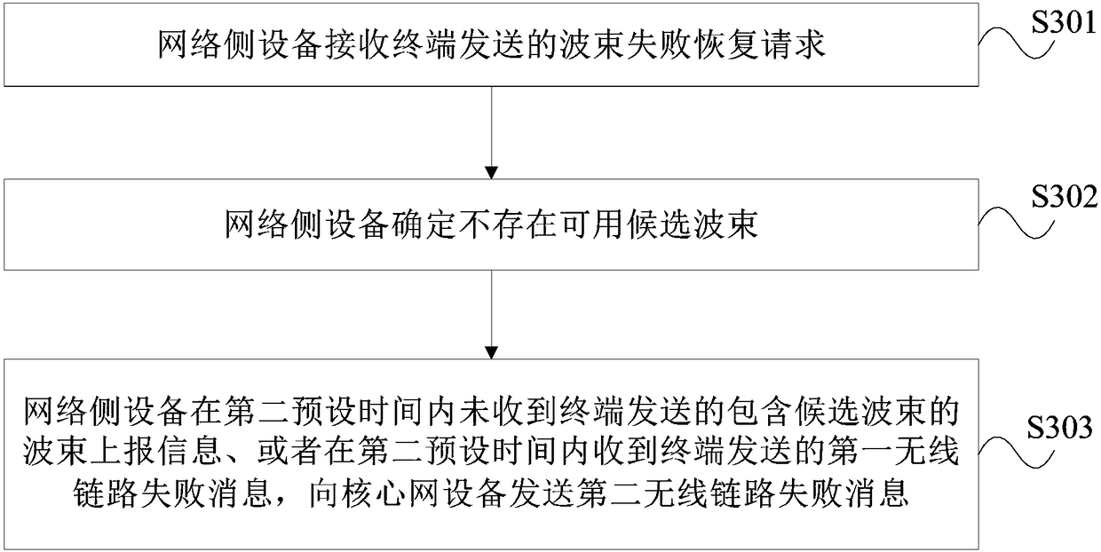
The invention provides a beam failure recovery processing method, a terminal and a network side device. The method comprises the following steps: the terminal sends a beam failure recovery request tothe network side device; and if the terminal determines that there is no available candidate beam, the terminal performs candidate beam measurement within a first preset time. That is, after the terminal measures beam failure, if there is no available candidate beam, the terminal does not report link failure at first, but waits for a period of time, and performs candidate beam measurement within the period of time so as to ensure the physical layer recovery beam of interaction between the terminal and the network side as much as possible, so that unnecessary recovery delay is shortened.

Description

technical field [0001] The present application relates to wireless communication technologies, and in particular to a beam failure recovery processing method, terminal and network side equipment. Background technique [0002] In the future 5G (5Generation, fifth generation) mobile communication system, in order to achieve the target of a downlink transmission rate of 20 megabits per second (Gbps) and an uplink transmission rate of 10 Gbps, high-frequency communication and large-scale antenna technology will be adopted. introduce. Specifically, high-frequency communication can provide wider system bandwidth and smaller antenna size, which is more conducive to the deployment of large-scale antennas in base stations and terminals. However, high-frequency communication has disadvantages such as large path loss, susceptibility to interference, and fragile links, and large-scale antenna technology can provide large antenna gain. Therefore, the combination of high-frequency commun...

Claims


Application Information

Patent Timeline
IPC IPC(8): H04W72/04H04W72/08
CPCH04W72/046H04W72/542
Inventor 孙晓东杨晓东陈力
Owner VIVO MOBILE COMM CO LTD
Learn More