A laser cavitation surface pretreatment device and method

A surface pretreatment and cavitation technology, which is applied in laser welding equipment, metal processing equipment, welding equipment, etc., can solve problems such as ablation of carbon fiber materials, carbon fiber material cracks, fractures, etc., to improve surface bonding strength, easy to glue connection, high surface quality

Active Publication Date: 2020-11-20
JIANGSU UNIV
View PDF5 Cites 0 Cited by
  • Summary
  • Abstract
  • Description
  • Claims
  • Application Information

AI Technical Summary

Problems solved by technology

Laser processing is a non-polluting, high-efficiency, non-contact precision processing technology, but due to the laser thermal diffusion effect, it is easy to ablate the carbon fiber material while processing the surface, resulting in cracks or breakage of the carbon fiber material

Method used


Image

  • A laser cavitation surface pretreatment device and method
  • A laser cavitation surface pretreatment device and method
  • A laser cavitation surface pretreatment device and method

Examples


Embodiment 1

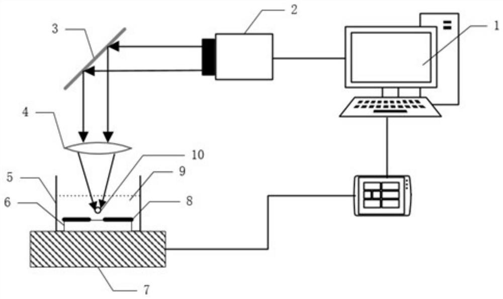
[0043] Select the material 6 to be treated as T300 / epoxy resin composite material, the surface is impurities to be treated and epoxy resin, place the material 6 to be treated in the container 5 and add liquid medium 9 as water, so that the upper surface of the material is at a height distance from the water surface h=5mm; the container 5 is placed on the mobile platform 7, and the movement of the mobile platform 7 is controlled by the control system 1, so that the distance between the impurities 8 on the upper surface of the material and the focal plane of the focusing lens 4 is h 0 =1 mm; the direction of the laser beam is adjusted by the scanning galvanometer 3 so that it is parallel to the normal direction of the upper surface of the material 6 to be processed.

[0044] Set laser energy, J 0 +J 1 +J 2 ≤J≤J 0 +J 2 +J 3 . Among them, J 0 =J w (1+αh),α=14.6171m -1 , J w =0.4mJ,J 0 =0.6mJ;J 1 = 15mJ; J 2 =5mJ;J 3 = 60mJ. That is, 21mJ≤J≤66mJ. Set the laser energ...

Embodiment 2

[0047] Select material 6 to be treated as T300 / epoxy resin composite material, the surface is impurity to be processed and epoxy resin, material 6 to be treated is placed in container 5 and then adding liquid medium 9 is 10% glycerin aqueous solution, so that the distance between the upper surface of the material The liquid surface height distance h=5mm; the movement of the mobile platform 7 is controlled by the control system 1, so that the distance between the impurities 8 on the upper surface of the material and the focal plane of the focusing lens 4 is increased to h 0 =2mm; the direction of the laser beam is adjusted by the scanning galvanometer 3 so that it is parallel to the normal direction of the upper surface of the material 6 to be processed. The laser energy was increased to J=50mJ.

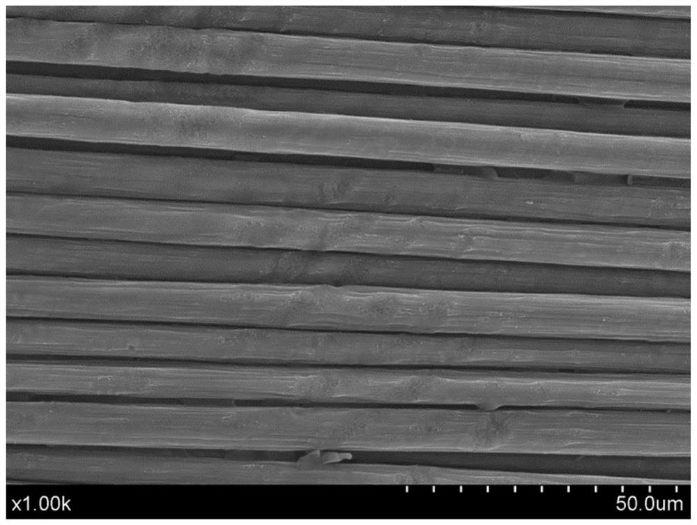
[0048] Such as image 3 Shown as J=50mJ, h=5mm, h 0 =2mm SEM images of laser cavitation surface pretreatment of carbon fiber composite materials. It is found from the images that th...

Embodiment 3

[0050] All preparations are the same as in Example 1, and the distance between the upper surface of the material and the height of the water surface is increased to be h=10mm; the impurity 8 on the upper surface of the material and the focal plane distance of the focusing lens 4 are h 0 =2mm; laser energy J=50mJ.

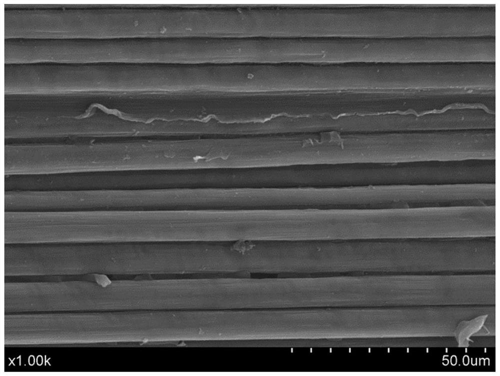
[0051] Such as Figure 4 Shown as J=50mJ, h=10mm, h 0 =2mm SEM image of carbon fiber composite material laser cavitation surface pretreatment, it is found from the image that the surface removal effect is better, the carbon fiber matrix is ​​complete, and there is no fracture. Compared with Example 1, the energy loss increases, the removal area expands, the surface has almost no undulations, and the modification effect is poor.


PUM


Abstract

The invention provides a laser cavitation surface pretreatment device and method. Materials to be treated are fiber materials, and impurities exist on the surfaces of the materials to be treated. Thedevice further comprises a pulse laser focusing device, a container and a control system. A liquid medium is contained in the container, the materials to be treated are soaked in the liquid medium, and the pulse laser focusing device is used for producing pulse laser and focusing the pulse laser to the impurities of the materials to be treated. The control system is used for controlling the pulselaser focusing device. The pulse laser focusing device comprises a pulse laser device, a scanning galvanometer and a focusing lens, and the scanning galvanometer and the focusing lens are located on alight path of the pulse laser device. Laser can be used for stimulate cavitation in the liquid medium to pretreat the surfaces of the carbon fiber materials, laser is prevented from excessively burning the carbon fiber materials, a surface micro-nano fine structure is formed, and the surface binding strength is improved.

Description

technical field [0001] The invention relates to the field of laser processing, in particular to a laser cavitation surface pretreatment device and method. Background technique [0002] Carbon fiber composite materials are widely used in aircraft manufacturing, wind power blades and other fields. Carbon fiber composite materials are mainly reinforced by adhesive bonding, and the performance of the bonding surface directly affects the bonding strength of the material. Surface pretreatment before bonding includes direct cleaning of impurities such as oil and surface modification of sheet materials. After pretreatment, the roughness of the bonding surface can be increased and the surface bonding strength of carbon fiber composite materials can be improved. [0003] The existing carbon fiber composite surface pretreatment technologies are mainly chemical treatment and manual grinding. Chemical treatment puts carbon fibers in HNO 3 Oxidation treatment in the solution, adjusting...

Claims


Application Information

Patent Timeline
Patent Type & Authority Patents(China)
IPC IPC(8): B23K26/352B23K26/00B23K26/146
CPCB23K26/146B23K26/352
Inventor 佟艳群王超任旭东韩奎国符永宏张昂杨宁周建忠
Owner JIANGSU UNIV
Why Eureka
Try Eureka