Clamping tooling with high stability

A technology for clamping tooling and stability, applied in the direction of workpiece clamping devices, positioning devices, clamping devices, etc., can solve problems such as instability, inconvenient clamping, and insufficient stability, and achieve the effect of novel structure

Inactive Publication Date: 2018-11-16
安徽龙锐模塑有限公司
View PDF0 Cites 25 Cited by
  • Summary
  • Abstract
  • Description
  • Claims
  • Application Information

AI Technical Summary

Problems solved by technology

Clamping tooling is widely used in mechanical processing, but the current clamping tooling on the market drives the splint to clamp the two opposite sides of the workpiece through the driving device. This clamping method is not stable enough in use. And the height of the splint is fixed. When the thickness of the workpiece does not match the thickness of the splint, the clamping is inconvenient and unstable. Therefore, it is necessary to improve the existing clamping tooling to improve the clamping stability.

Method used


Image

  • Clamping tooling with high stability

Examples


Embodiment Construction

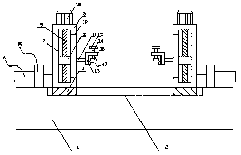
[0012] Such as figure 1 As shown, the present invention discloses a clamping tool with high stability, including: a base 1, a chute 2, a mounting seat 3, a bump 4, a fixed block 5, a cylinder 6, a rectangular through groove 7, a slider 8, Screw rod 9, motor 10, connecting rod 11, strip hole 12, L-shaped plate 13, screw rod 14, handle 15, briquetting block 16, splint 17, a chute 2 is respectively provided on the inner and outer sides of the upper end surface of the base 1, And the two chutes 2 are parallel to each other, and the left and right sides of the upper end surface of the base 1 are respectively slidably provided with a mounting seat 3 , and the inner and outer sides of the lower end surface of the mounting seat 3 are fixedly connected with protrusions 4 matching the chute 2 , the mounting seat 3 is slidingly connected with the slide groove 2 through the protrusion 4, and the fixing blocks 5 are two symmetrical and vertically fixed on the left and right sides of the up...


PUM


Abstract

The invention discloses a clamping tooling with the high stability. Slide grooves are formed in the inner and outer sides of the upper end surface of a base correspondingly. Mounting bases are arranged on the left and right sides of the upper end surface of the base in a sliding mode correspondingly. Piston rods of air cylinders penetrate through fixing blocks and are fixedly connected with the mounting bases on the same sides correspondingly. Longitudinal rectangular grooves are formed in the mounting bases correspondingly. Lead screws are rotationally mounted in the rectangular grooves correspondingly through bearings, penetrate through slide blocks and are in threaded connection with threaded holes of the slide blocks correspondingly. Output shafts of motors are fixedly connected with the upper ends of the lead screws correspondingly. The end surfaces, facing the center side of the base, of the slide blocks are horizontally and fixedly connected with connecting rods correspondingly.Strip-shaped holes allowing the connecting rods to penetrate through are formed in the end surfaces, facing the center side of the base, of the mounting bases correspondingly. The other ends of the connecting rods are fixedly connected with L-shaped plates correspondingly. The upper portion of a horizontal portion of each L-shaped plate is in threaded connection with a screw vertically. The upperend of each screw is fixedly connected with a handle. The lower end of each screw is fixedly connected with a pressing block. A clamping plate is fixedly connected to the end surface, facing the center side of the base, of a vertical portion of each L-shaped plate. The clamping tooling has the advantages of being novel in structure and stable in clamping.

Description

technical field [0001] The invention relates to a clamping tool with high stability, which is applied in the technical field of mechanical processing. Background technique [0002] Fixture refers to the device used to fix the processing object in the process of mechanical manufacturing so that it occupies the correct position to accept construction or inspection. Clamping tooling is widely used in mechanical processing, but the current clamping tooling on the market drives the splint to clamp the two opposite sides of the workpiece through the driving device. This clamping method is not stable enough in use. Moreover, the height of the splint is fixed. When the thickness of the workpiece does not match the thickness of the splint, the clamping is inconvenient and unstable. Therefore, it is necessary to improve the existing clamping tooling to improve the clamping stability. Contents of the invention [0003] In order to solve the defects of the prior art solutions, the in...

Claims


Application Information

Patent Timeline
Patent Type & Authority Applications(China)
IPC IPC(8): B23Q3/08B25B11/00
CPCB23Q3/08B23Q2703/04B25B11/00
Inventor 周莉
Owner 安徽龙锐模塑有限公司
Why Eureka
Try Eureka