Supercharge Your Innovation With Domain-Expert AI Agents!

Mechanical hand for engineering

A manipulator and engineering technology, applied in manipulators, manufacturing tools, chucks, etc., can solve the problems of people climbing on the machine, danger, parts flying to the machine, etc., to facilitate replacement and maintenance, prolong service life, and prevent falling off.

Active Publication Date: 2018-11-16
新昌县凌智机械有限公司
View PDF6 Cites 0 Cited by
  • Summary
  • Abstract
  • Description
  • Claims
  • Application Information

AI Technical Summary

Problems solved by technology

[0002] In normal work activities, parts often fly into the machine due to improper operation, or when an item in a large machine needs to be taken, for safety reasons, the machine is often stopped and then taken by hand. When the machine is too large, it is not easy to get the parts, and it is very dangerous for people to climb on the machine
[0003] In many cases, people will use manipulators to pick them up, but many manipulators do not have protective measures, they cannot protect the palms and arms well, and the operation is cumbersome and troublesome to use.

Method used


Image

  • Mechanical hand for engineering
  • Mechanical hand for engineering
  • Mechanical hand for engineering

Examples


Embodiment 1

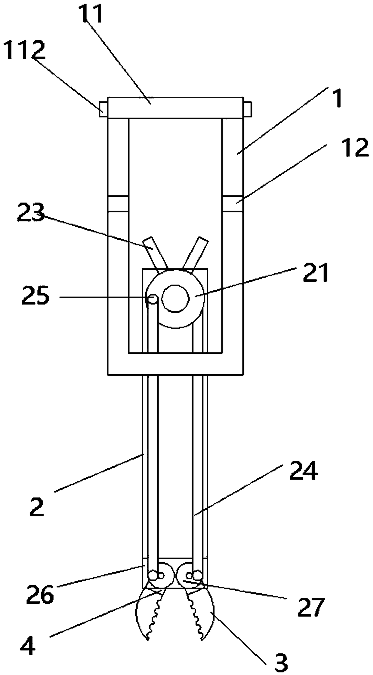
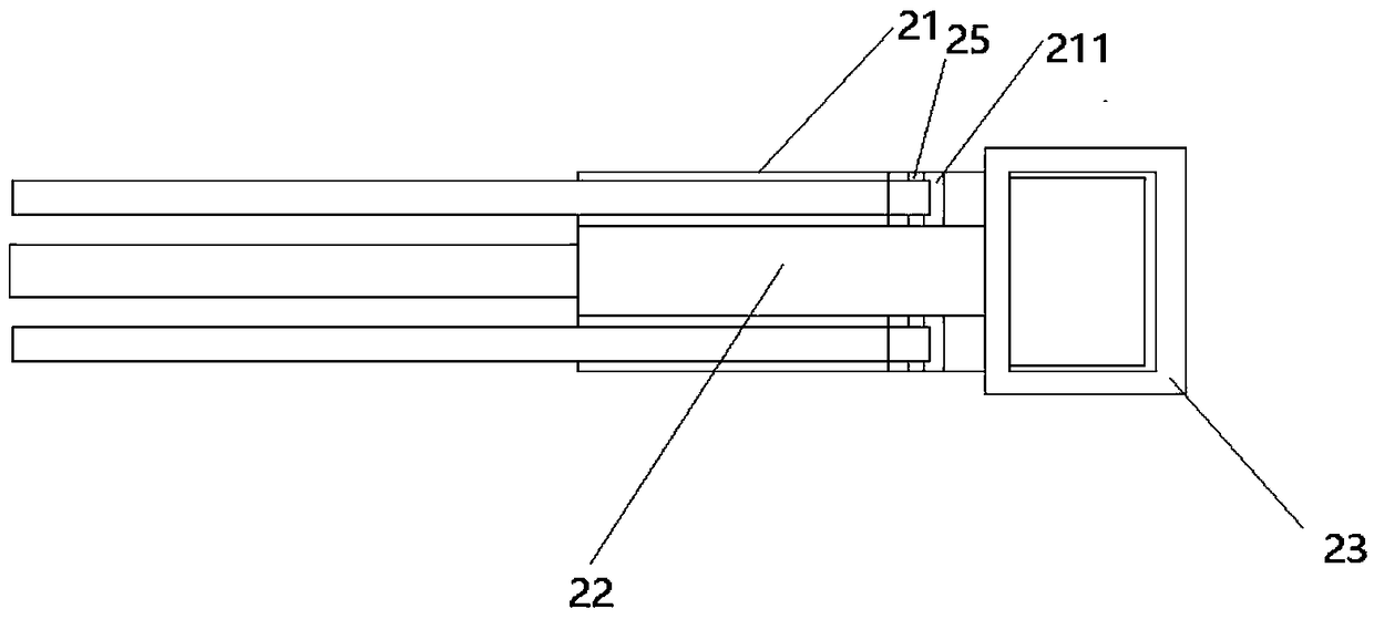
[0024] An engineering manipulator, comprising: a collar 1, a mechanical arm 2 and a mechanical finger 3, such as figure 1 As shown, the upper end of the collar 1 is provided with a collar 11, the lower end of the collar 11 is slidingly connected with the collar 1, the collar shaft 12 is arranged in the middle of the collar 1, and the collar 1 at the upper and lower ends is connected through the collar shaft 12. The lower end of the ring 1 is rotationally connected with the mechanical arm 2, and a handle shaft is provided on the inner side of the upper end of the mechanical arm 2, and the handle shaft includes an outer shaft 21 and an inner shaft 22, such as image 3 As shown, an inner shaft 22 is arranged in the middle of the outer shaft 21, and the outer shaft 21 is connected to the inner shaft 22 by passing the rivet through the hole in the middle of the outer shaft 21 and the inner shaft 22. The side is provided with connection port 211, and connection port 211 is provided ...

Embodiment 2

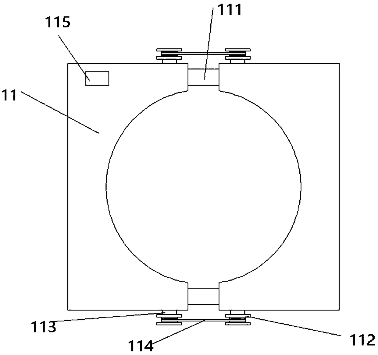
[0026] The difference between this embodiment and embodiment 1 is that, as figure 2 As shown, the inside of the left and right ends of the sleeves 11 is semicircular, the sleeves 11 at both ends are slidably connected by the sleeve connecting rod 111, the upper and lower ends of the sleeve 11 are provided with a sleeve connecting shaft 112, and the sleeve connecting shaft 112 passes through the sleeve. The connecting column 113 is fixedly connected with the socket motor in the socket 11, the socket connecting shafts 112 at the left and right ends are connected by a connecting belt 114, and a socket controller 115 is provided on the socket 11 upper end.

[0027] When in use, separate the sleeves 11 at both ends, put the arm into the circular groove inside the sleeve 11, press the sleeve controller 115 to control the motor in the sleeve 11 to rotate, so that the sleeves 11 on both sides are closed and wrapped The motor in the rear pocket 11 of the arm stops working, and when no...

Embodiment 3

[0029] The difference between this embodiment and embodiment 1 is that, as Figure 4 As shown, the lower end of the finger shaft connection block 4 is provided with a finger shaft connection hole 41, the finger shaft connection hole 41 is an internal thread structure, the upper end of the mechanical finger 3 is fixed with a mechanical finger cover 38, and the left and right sides of the mechanical finger cover 38 are fixed with telescopic tubes 36, Telescopic tube 36 outside is provided with telescopic rod 31, and telescopic rod 31 right side is provided with telescopic block 35, and telescopic block 35 is connected with telescopic tube 36 by spring 37, and telescopic rod 31 outside is provided with screw cap 32, and screw cap 32 right side is fixed with The screw rod 33 is provided with a screw connection block 34, the left side of the screw rod 33 passes through the telescopic rod 31 and is fixedly connected with the screw cap 32, and the right side of the screw rod 33 passes...


PUM


Abstract

The invention provides a mechanical hand for engineering. The mechanical hand comprises sleeve rings, mechanical arms and mechanical fingers, wherein sleeve holes are formed in the upper ends of the sleeve rings; the lower ends of the sleeve holes are in sliding connection with the sleeve rings; sleeve ring shafts are arranged on the middle parts of the sleeve rings; the sleeve rings at upper andlower ends are rotatably connected through the sleeve ring shafts; the lower ends of the sleeve rings are rotatably connected with the mechanical arms; handle shafts are arranged at inner sides of theupper ends of the mechanical arms; each handle shaft comprises outer shafts and an inner shaft, wherein the inner shaft is arranged between the outer shafts, a rivet passes through middle holes of the outer shafts and a middle hole of the inner shaft for enabling the outer shafts to rotatably connect with the inner shaft, the outer shafts and the right side of the inner shaft are connected with handles; the left sides of the handles are equipped with connecting holes; connecting blocks are arranged in the connecting holes; the connecting blocks pass through holes in the right sides of connecting columns and are rotatably connected with the connecting columns; finger slots are formed in the lower ends of the mechanical arms; finger shafts are arranged in the finger slots; the finger shaftsare rotatably connected with the finger slots; connecting blocks are arranged in the finger shafts; connecting blocks in the finger shafts are rotatably connected with the connecting columns; the lower ends of the finger shafts are fixedly equipped with finger shaft connecting blocks; and the lower ends of the finger shaft connecting blocks are detachably connected with the mechanical fingers. The mechanical hand is simple in use, is safe and is wide in range of application.

Description

technical field [0001] The invention relates to the technical field of engineering machinery, in particular to an engineering manipulator. Background technique [0002] In normal work activities, parts often fly into the machine due to improper operation, or when an item in a large machine needs to be taken, for safety reasons, the machine is often stopped and then taken by hand. When the machine is too large, it is not easy to get parts, and it is very dangerous for people to climb on the machine. [0003] In many cases, people will use manipulators to pick them up, but many manipulators do not have protective measures, they cannot protect the palms and arms well, and the operation is cumbersome and troublesome to use. Contents of the invention [0004] The technical problem solved by the present invention is to provide an engineering manipulator to solve the problems raised in the above-mentioned background technology. [0005] The technical problem solved by the prese...

Claims


Application Information

Patent Timeline
IPC IPC(8): B25J15/02
CPCB25J15/0206
Inventor 许炳初
Owner 新昌县凌智机械有限公司
Features
  • R&D
  • Intellectual Property
  • Life Sciences
  • Materials
  • Tech Scout
  • Unparalleled Data Quality
  • Higher Quality Content
  • 60% Fewer Hallucinations
Learn More