Positioning installation mold

A positioning installation and mold technology, which is applied in transportation and packaging, ship parts, ships, etc., can solve the problems of long positioning and installation time, low installation accuracy, and easy deformation, so as to improve installation efficiency, improve positioning and installation accuracy, reduce Effect of installation error and deformation

Active Publication Date: 2018-11-16
SHANGHAI WAIGAOQIAO SHIP BUILDING CO LTD
View PDF7 Cites 3 Cited by
  • Summary
  • Abstract
  • Description
  • Claims
  • Application Information

AI Technical Summary

Problems solved by technology

[0003] The technical problem to be solved by the present invention is to provide a positioning and installation mold in order to overcome the defects of long actual position

Method used


Image

  • Positioning installation mold
  • Positioning installation mold
  • Positioning installation mold

Examples


Embodiment 1

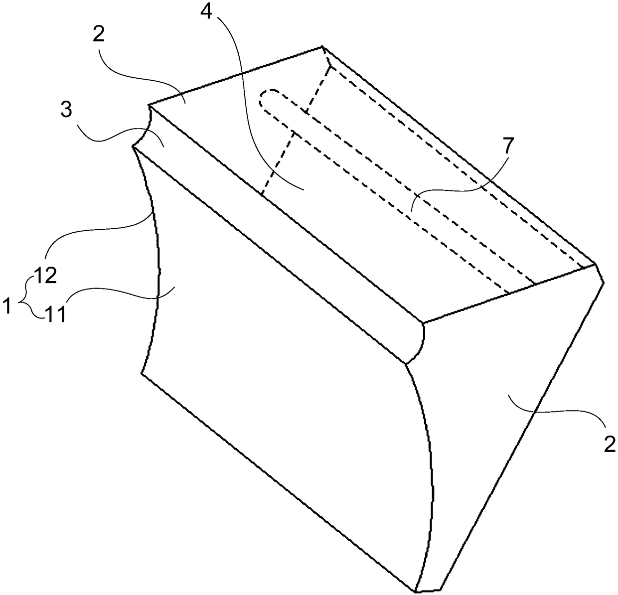
[0047] Such as figure 1 As shown, Embodiment 1 of the present invention discloses a positioning installation mold for positioning and installing the bilge keel (not shown in the figure) on the bilge part of the hull (not shown in the figure); the positioning installation mold includes an arc Plate 1, positioning part and two supporting plates 2, the two supporting plates 2 are respectively connected to the arc segments 11 at both ends of the arc-shaped plate 1, the positioning part is connected between the two supporting plates 2, and the positioning part is connected to the arc-shaped plate 1; The arc surface section 12 of the arc plate 1 matches the shape of the outer surface of the bilge and the arc plate 1 is attached to the bilge, the plane where the positioning portion is located passes through the center of curvature of the outer surface of the bilge, and the positioning portion and the bilge keel align.

[0048] Specifically, compared with the middle area of ​​the hul...

Embodiment 2

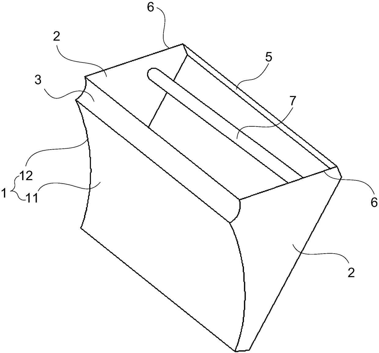
[0065] Such as figure 2 As shown, Embodiment 2 of the present invention discloses a positioning installation mold.

[0066] In this embodiment, part of the structure of the positioning installation mold is the same as that of the positioning installation mold in Embodiment 1, the difference is that the positioning part is designed as a hollow structure.

[0067] In the positioning installation mold of this embodiment, the positioning part includes a connecting rod 5 and two straight segments 6, the straight segment 6 corresponds to the supporting plate 2 one by one and the straight segment 6 is arranged on the supporting plate 2, and the connecting rod 5 is arranged on the positioning part At one end away from the arc-shaped plate 1 , a connecting rod 5 is connected between two straight sections 6 .

[0068] The positioning part is set as the structure of the connecting rod 5 and the two straight sections 6, so as to ensure the basic positioning installation and the function...

Embodiment 3

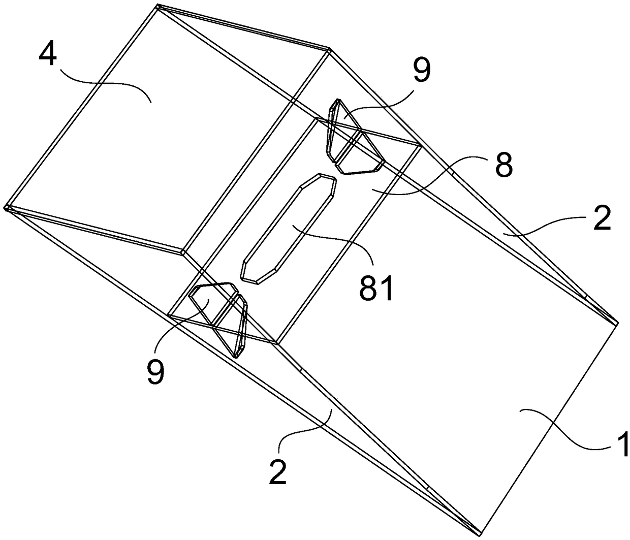
[0070] Such as image 3 As shown, Embodiment 3 of the present invention discloses a positioning installation mold.

[0071] In this embodiment, part of the structure of the positioning and installation mold is the same as that of the positioning and installation mold in Embodiment 1, the difference is that the gripping part is a plate-shaped structure.

[0072] In the positioning and installation mold of this embodiment, the gripping part is a reinforcing plate 8 , and a through hole 81 for gripping is opened in the reinforcing plate 8 , and both ends of the reinforcing plate 8 are respectively connected to the support plate 2 through a reinforcing piece 9 .

[0073] The grip part is designed as a plate structure with a through hole 81 to increase the strength between the grip part and the two support plates 2, and avoid the defect that the positioning and installation mold itself deforms after repeated use, resulting in a decrease in positioning and installation accuracy.

...


PUM


Abstract

The invention provides a positioning installation mold for positioning and installing a bilge keel in a bilge area of a hull; the positioning installation mold comprises a curved plate, a positioningportion and two support plates, wherein the two support plates are respectively connected to an arc segment at both ends of the curved plate, the positioning portion is connected between the two support plates, the positioning portion is connected with the curved plate; the arc segment of the curved plate matches the outer surface shape of the bilge area and the curved plate fits over the bilge area, the plane in which the positioning portion lies passes through the curvature center of the outer surface of the bilge area, and the positioning portion is aligned with the bilge keel. The positioning installation mold improves the installation efficiency of the bilge keel, improves the positioning installation precision of the bilge keel, reduces the installation error and deformation, thus, the work of repairing and closing the bilge keel caused by the second opening of the dock is avoided, the construction difficulty is reduced, and the ship performance is improved. In addition, shipbuilding costs and labor hours are reduced.

Description

technical field [0001] The invention relates to the technical field of ship bilge keel installation, in particular to a positioning and installation mold. Background technique [0002] At present, the bilge keel is installed in the fore and aft bilge keel area of ​​the ship, and the single-piece combined template is used as the mold for positioning and installing the bilge keel. Its thickness is about 10 mm, and the purpose is to determine the positioning and installation angle of the bilge keel. The single-piece model can control the installation and positioning angle of the bilge keel well in the parallel midbody area of ​​the ship, but it is not perfect in the fore and aft line area of ​​the ship, and there are numerical deviations, and it needs to be used repeatedly in multiple positions to roughly ensure After the positioning and installation is completed, the general shipyards use this simple single-piece model to position and install the bilge keel, which takes a long...

Claims


Application Information

Patent Timeline
IPC IPC(8): B63B9/00
CPCB63B71/00Y02T70/10
Inventor 朱文斌陶寅之
Owner SHANGHAI WAIGAOQIAO SHIP BUILDING CO LTD
Why Eureka
Try Eureka