Ultrasonic-frequency heating equipment for whole uniform heating of variable cross-section rod piece

A technology of heating equipment and uniform heating, which is applied in the direction of heat treatment equipment, heat treatment furnace, process efficiency improvement, etc. It can solve the problems of complicated and difficult operation of heating equipment, uneven heating of stabilizing rods, etc., so as to avoid fatigue failure, same hardness, heating consistent temperature effect

Inactive Publication Date: 2018-11-16
滁州硕燊机械制造有限公司
View PDF1 Cites 0 Cited by
  • Summary
  • Abstract
  • Description
  • Claims
  • Application Information

AI Technical Summary

Problems solved by technology

[0005] The purpose of the present invention is to solve the problems of uneven overall heating of the stabilizer bar and complicated and difficult-to-operate heating equipment in the prior art, and to provide a supersonic heating equipment for uniformly heating the entire variable-section rod to solve the above problems

Method used


Image

  • Ultrasonic-frequency heating equipment for whole uniform heating of variable cross-section rod piece
  • Ultrasonic-frequency heating equipment for whole uniform heating of variable cross-section rod piece
  • Ultrasonic-frequency heating equipment for whole uniform heating of variable cross-section rod piece

Examples


Embodiment 1

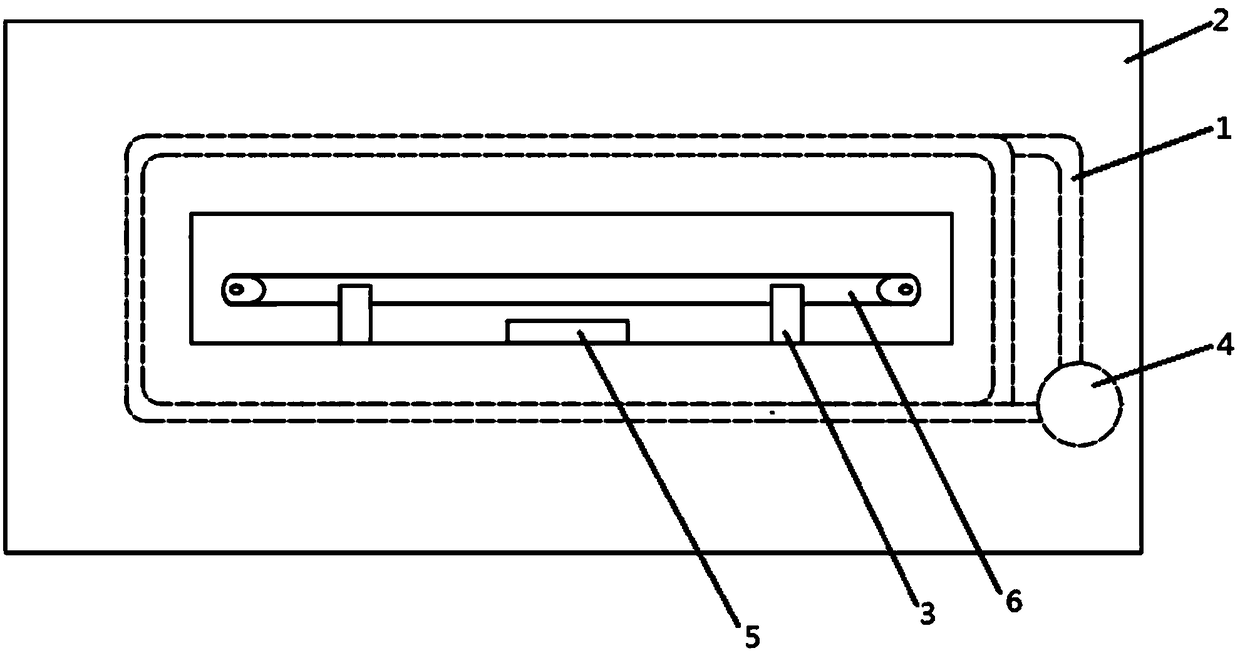
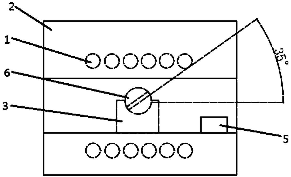
[0022] Embodiment one, such as figure 1 figure 2 As shown, the present invention discloses a supersonic audio heating device for uniformly heating the entire variable-section rod, including a heating coil 1, an insulating casing 2, and at least two horizontally arranged along the winding direction of the heating coil 1 for placing variable-section rods. The positioning part 3 of the rod, the supersonic heating power supply 4 and the temperature detector 5. The heating coil 1 is located in the insulating casing 2 ; the insulating casing 2 is provided with a through hole along the opening axis direction of the heating coil 1 . The through hole is located in the cavity of the heating coil 1 . The positioning piece 3 is located in the through hole and surrounded by the heating coil 1 , and a groove is provided in the middle of the upper end surface of the positioning piece 3 . The axis of the groove is perpendicular to the opening axis of the heating coil 1. The rod body of th...

Embodiment 2

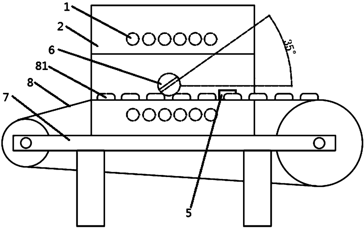
[0025] Embodiment two, such as image 3 As shown, in actual work, the crawler conveyor belt 8 can also be used instead of the positioning member 3 . Crawler conveyor belt 8 is fixed on the frame 7. During work, the variable section rod 6 is placed between two adjacent track shoes 81, the rod body of the variable section rod 6 is limited by using the gap between the adjacent track shoes 81, and the variable section of the variable section rod 6 is adjusted. The included angle with the opening axis of the heating coil 1 is within the range of 30°-40°. Afterwards, the crawler conveyor belt 8 is started to send the variable-section rod 6 into the supersonic heating equipment, and the heating coil 1 is started to heat the variable-section rod 6 . The probe of the temperature detector 5 detects the temperature of the variable section rod 6 . When the temperature reaches the set value, the temperature detector 5 sends an alarm signal, the power supply can be disconnected, the heat...


PUM


Abstract

The invention discloses ultrasonic-frequency heating equipment for the whole uniform heating of a variable cross-section rod piece. The ultrasonic-frequency heating equipment comprises a heating coil,an insulating shell and a positioning piece; the heating coil is located in the insulating housing, a penetrating through hole is formed in the insulating shell in the axial direction of an opening of the heating coil, the positioning piece is located in the coil, and a groove is formed in the middle of the upper end face of the positioning piece; and the axis of the groove is perpendicular to the axis of the opening of the heating coil, a rod body of a variable cross-section rod is placed in the groove, and the included angle between the variable cross sections of the two ends of the variable cross-section rod and the axis of the opening of the heating coil is any angle within 30-40 degrees. Compared with the prior art, the forging plane at the end of the rod piece and the axis of the opening of a ultrasonic-frequency heater tilt by 30-40 degrees, the fact that the eddy current line is most suitable to penetrate through the plane projection area at the end is ensured, and the goal ofthe consistent overall heating temperature of the rod body is achieved; and the transformation and the hardness of the end head and the middle part of the variable cross-sectional rod is consistent,and the occurrence of fatigue failure of the variable cross-sectional rod is effectively avoided.

Description

technical field [0001] The invention relates to a heating device, in particular to a super-audio frequency heating device for uniformly heating the entire variable-section rod. Background technique [0002] At present, in the production industry of automobile stabilizer bars, a commonly used process is to first conduct resistance heating on the stabilizer bar blank, and then use a special forming machine to bend it in a hot state, and then quench it. Among them, the equipment usually used in resistance heating includes two pairs of heating electrodes. Select the electrode clamping point at the middle part of the two ends of the stabilizer bar at a certain distance from the end, place the rod body, and the heating electrodes clamp the stabilizer bar. In this way, the two pairs The part of the rod body between the heating electrodes and the electrodes form a loop, and the middle part of the stabilizer rod is equivalent to a resistor. After the power is turned on, the resistanc...

Claims


Application Information

Patent Timeline
Patent Type & Authority Applications(China)
IPC IPC(8): C21D1/42C21D9/00
CPCC21D1/42C21D9/0075Y02P10/25
Inventor 王家文
Owner 滁州硕燊机械制造有限公司
Why Eureka
Try Eureka