An overall super-audio frequency heating equipment for variable cross-section rods

A technology of heating equipment and variable section, applied in heating/cooling equipment, metal processing equipment, manufacturing tools, etc., can solve complex and difficult to operate, easy to deform heating equipment, uneven heating of stabilizer bars, etc., to avoid fatigue failure, The effect of low deformation and high temperature deformation prevention

Active Publication Date: 2021-03-16
滁州宇美塑业有限公司
View PDF4 Cites 0 Cited by
  • Summary
  • Abstract
  • Description
  • Claims
  • Application Information

AI Technical Summary

Problems solved by technology

[0006] The purpose of the present invention is to solve the problems in the prior art that the overall heating of the stabilizer bar is uneven and easy to deform, and the heating equipment is complicated and difficult to operate, and provides an overall super-audio frequency heating equipment for variable cross-section rods to solve the above problems

Method used


Image

  • An overall super-audio frequency heating equipment for variable cross-section rods
  • An overall super-audio frequency heating equipment for variable cross-section rods
  • An overall super-audio frequency heating equipment for variable cross-section rods

Examples


Embodiment 1

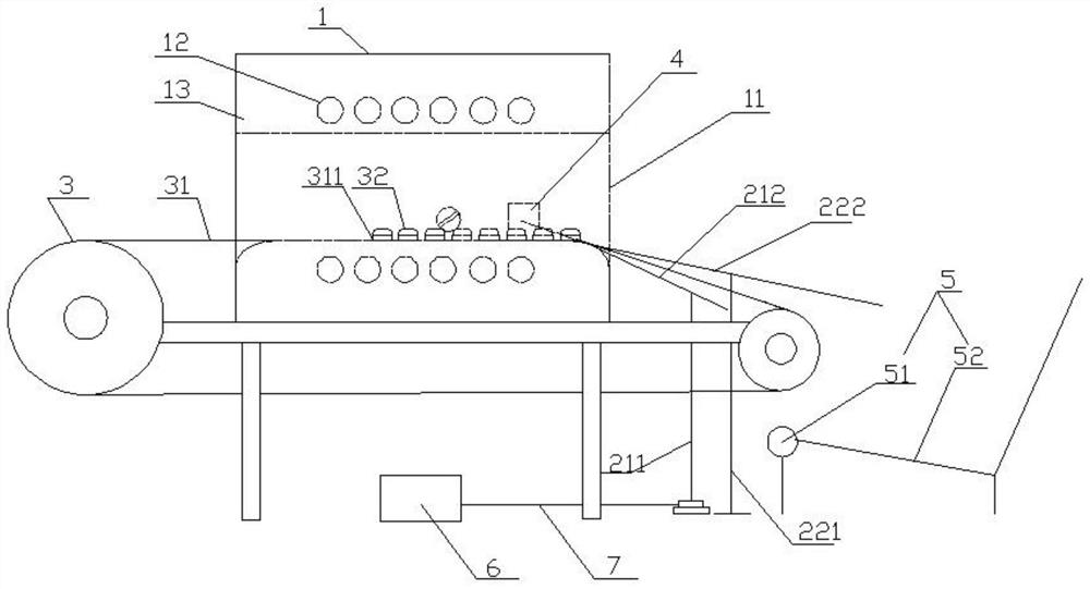
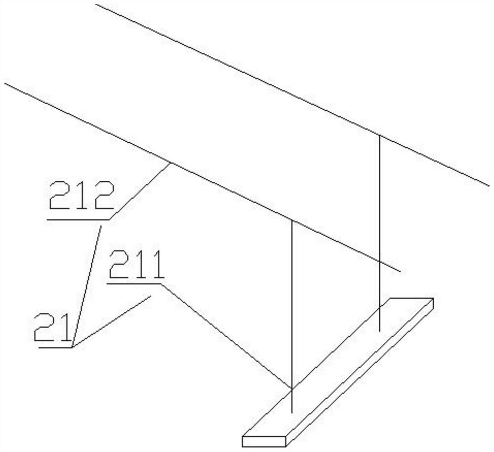
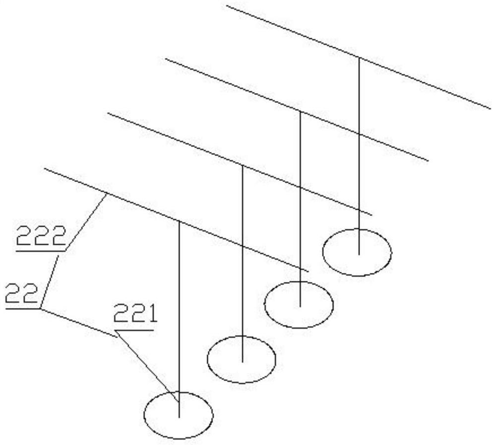
[0034]Embodiment one, such as figure 1 , figure 2 , image 3 The shown heating device includes two sets of shift forks 21 and four sets of conveying mechanisms 22 , and the brackets 1 212 of the two sets of shift forks 21 are arranged on the same base.

[0035] In specific work, several workpieces to be heated are successively sent to the heater of the heating device by the conveyor belt 31 , and the limiting member 4 concentrates and restricts the workpieces to be heated in the heating area of ​​the heater 1 . After the workpiece is heated, the motor 6 is started. The motor 6 drives the shift fork 21 to move in an arc towards the direction of the discharge port 11 . During the movement, the support one 211 gradually rises and leans against the discharge port 11. Since the driving rod 212 is movably connected with the support one 211, the driving rod 212 is driven by the support one 211, and the driving rod 212 is connected to the discharge port 11. The overlapping end of...

Embodiment 2

[0038] Embodiment 2, the receiving device 5 , the shift fork 21 and the conveying device 22 can be independent, or they can be fixed on the frame of the heating equipment as required. Certainly, according to the frame structure difference of different heating equipments, in order that the receiving device 5, the shift fork 21 and the conveying device 22 can play their respective functions better, the support of the material receiving device 5, the shifting fork 21 and the conveying device 22 can be adjusted. The structure is slightly deformed to accommodate racks for heating equipment, such as Figure 6 shown.

[0039] In the second embodiment, on the frame of the heating equipment, a conveying mechanism 22 , two sets of shift forks 21 , and a material receiving device 5 are sequentially arranged outwardly from the discharge port 11 . The three cooperate with each other without interfering with each other. Wherein, two sets of shift forks 21 are fixed on a base, and the base...


PUM


Abstract

The invention discloses variable cross-section rod piece overall superaudio frequency heating equipment which comprises a superaudio frequency heating device used for heating an overall variable cross-section rod, a receiving device and a conveying mechanism. The heating device comprises a heating zone and a discharging opening, the conveying mechanism comprises a conveying belt used for feeding the variable cross-section rod to the heating zone, and the conveying belt is provided with a ceramic piece; and the receiving device is provided with an opening, and the output end of the conveying mechanism is located above the opening. Compared with the prior art, ceramic has the high melting point, the high high-temperature strength, the small high temperature creep property, the good resistance to heat shocks, good resistance to corrosion, good resistance to oxidation and the good structure stability and the like. The ceramic piece is used on the conveying belt, the conveying belt is prevented from being subjected to superaudio frequency induced magnetization, and high temperature deformation of the conveying belt is prevented. Compared with a traditional metal conveying belt, the service life of the conveying belt with the ceramic piece is greatly prolonged. Meanwhile, the conveying belt which is stable in structure and provided with the ceramic piece can guarantee that the deformation is reduced to be minimum after the variable cross-section rod is heated.

Description

technical field [0001] The invention relates to the technical field of heating, in particular to an integral super-audio frequency heating device for variable-section rods. Background technique [0002] At present, in the production industry of automobile stabilizer bars, a commonly used process is to first conduct resistance heating on the stabilizer bar blank, and then use a special forming machine to bend it in a hot state, and then quench it. Among them, the device usually used in resistance heating includes two pairs of heating electrodes. Select the electrode clamping point at the middle part of the two ends of the stabilizer bar at a certain distance from the broken end, place the rod body, and the heating electrodes clamp the stabilizer bar. In this way, the two pairs The part of the rod body between the heating electrodes and the electrodes form a loop, and the middle part of the stabilizer rod is equivalent to a resistor. After the power is turned on, the resistanc...

Claims


Application Information

Patent Timeline
Patent Type & Authority Patents(China)
IPC IPC(8): B21K29/00C21D1/42
CPCB21K29/00C21D1/42Y02P10/25
Inventor 王家文
Owner 滁州宇美塑业有限公司
Why Eureka
Try Eureka