A Whole Ultrasonic Heating Method for Variable Cross-section Rods

A heating method and variable cross-section technology, applied in vehicle parts, transportation and packaging, etc., can solve complex and difficult to operate, easy to deform heating equipment, uneven heating of stabilizer bars, etc., to avoid fatigue failure, low deformation, prevent The effect of high temperature deformation

Active Publication Date: 2020-04-28
ANHUI LIBA POWER LITHIUM BATTERY TECH
View PDF6 Cites 0 Cited by
  • Summary
  • Abstract
  • Description
  • Claims
  • Application Information

AI Technical Summary

Problems solved by technology

[0006] The purpose of the present invention is to solve the problems in the prior art that the overall heating of the stabilizer bar is uneven and easy to deform, and the heating equipment is complicated and difficult to operate, and provides an overall supersonic heating method for variable cross-section rods to solve the above problems

Method used


Image

  • A Whole Ultrasonic Heating Method for Variable Cross-section Rods
  • A Whole Ultrasonic Heating Method for Variable Cross-section Rods
  • A Whole Ultrasonic Heating Method for Variable Cross-section Rods

Examples


Embodiment 1

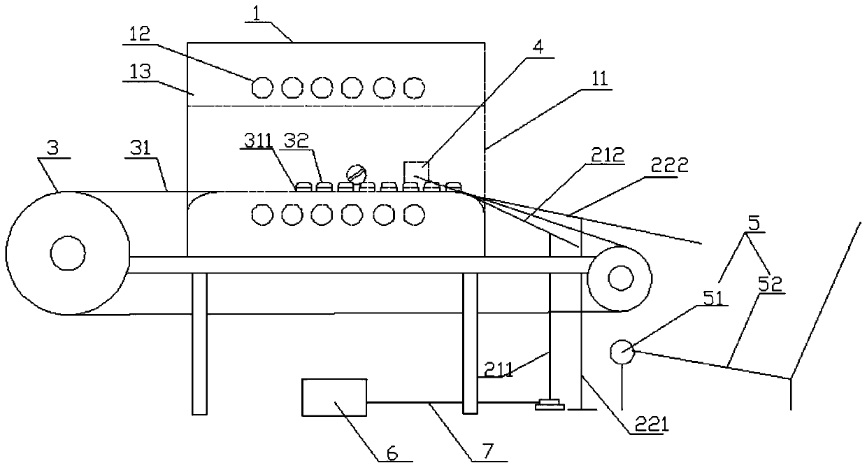
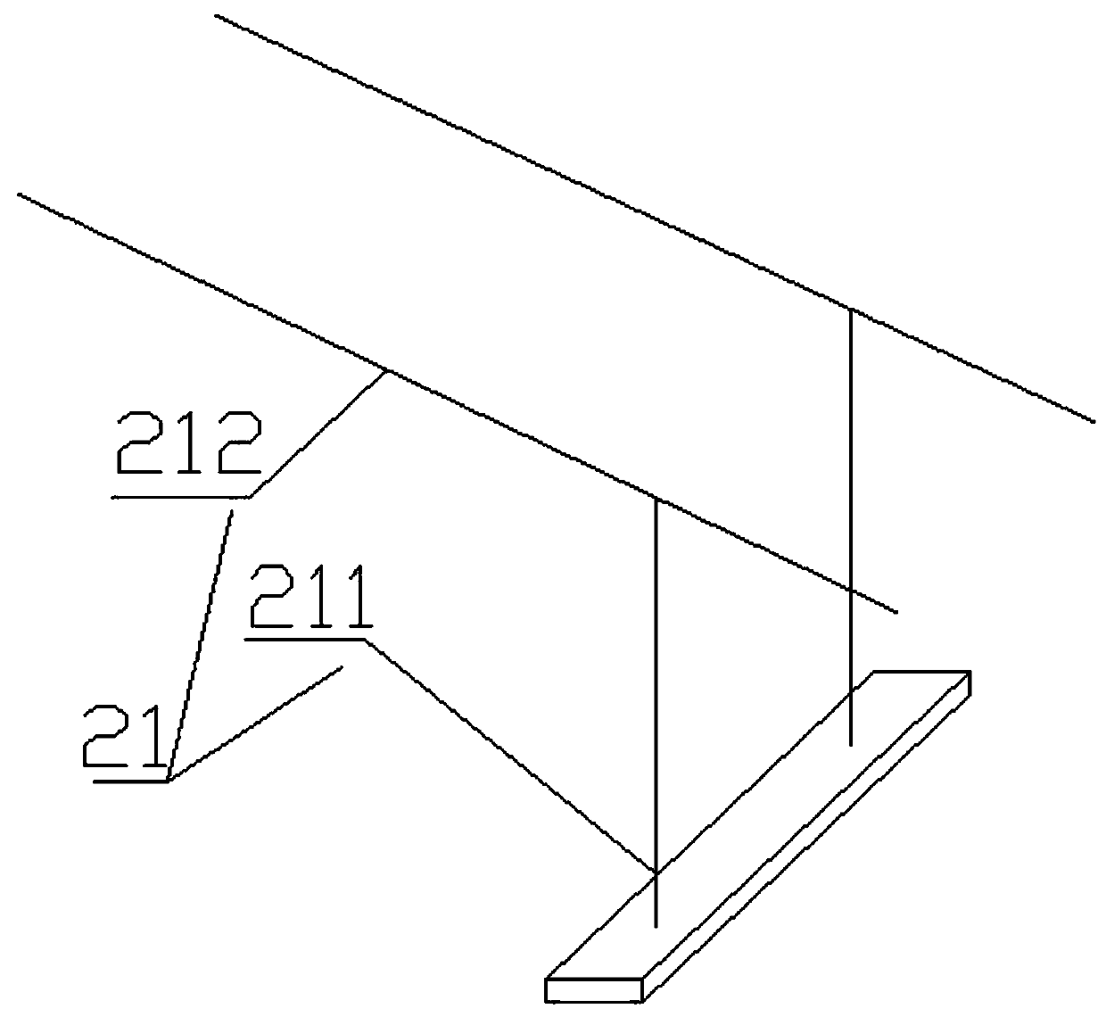
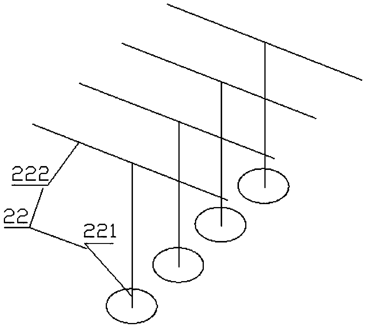
[0033] Embodiment one, such as figure 1 , figure 2 , image 3 The overall supersonic heating equipment with variable cross-section rods shown includes two sets of shift forks 21 and four sets of conveying mechanisms 22, and the brackets 1 212 of the two sets of shift forks 21 are arranged on the same base.

[0034] In specific work, several workpieces to be heated are successively sent to the heater of the overall supersonic heating equipment for variable-section rods by the conveyor belt 31, and the limiting member 4 concentrates and restricts the workpieces to be heated in the heating area of ​​the heater 1. After the workpiece is heated, the motor 6 is started. The motor 6 drives the shift fork 21 to move in an arc towards the direction of the discharge port 11 . During the movement, the support one 211 gradually rises and leans against the discharge port 11. Since the driving rod 212 is movably connected with the support one 211, the driving rod 212 is driven by the su...

Embodiment 2

[0037] In the second embodiment, the receiving device 5, the shift fork 21 and the conveying device 22 can be independent of each other, and can also be fixed on the frame of the overall supersonic frequency heating equipment of variable cross-section rods as required. Of course, according to the frame structure of the overall super-audio frequency heating equipment of different variable cross-section rods, in order to better play their respective functions for the material receiving device 5, the shift fork 21 and the conveying device 22, the material receiving device 5, the shift fork 21 and the support structure of conveying device 22 are slightly deformed to adapt to the frame of heating equipment, as Image 6 shown.

[0038] In the second embodiment, on the rack of the overall supersonic heating equipment for variable-section rods, a conveying mechanism 22 , two sets of shift forks 21 , and a material receiving device 5 are sequentially arranged outward from the discharge...


PUM


Abstract

The invention discloses an overall ultrasonic frequency heating method of a variable-cross-section rod. The overall ultrasonic frequency heating method of the variable-cross-section rod comprises thesteps: workpieces to be heated are successively conveyed to a heater of a heating device through a conveyor belt, and a limiting piece limits the workpieces to be heated in a heating area of the heater; a motor is started after the workpieces are heated so as to drive a shifting fork to circularly move toward the direction of a discharge hole; a support I is gradually elevated and gets close to the discharge hole; a driving lever is basically at the horizontal state finally under the drive of the support I, and an electrode starts to reset at the time so as to drive the support I to be far away from the discharge hole and reduce the height of the support I; and under the drive of the support I, a lap-joint point of the driving lever and the discharge hole is adopted as a support point, thefree end of the driving lever starts to lower down, a lap-joint end of the driving lever and the discharge hole starts to raise upwards so as to lift the heated workpieces, and the lifted workpiecesslide off along a lever body of the driving lever until falling into a receiving device. The overall ultrasonic frequency heating method of the variable-cross-section rod provided by the invention hasthe advantages that the service life of the conveyor belt is greatly prolonged, and the deformation amount of the variable-cross-section rod after being heated is reduced to the minimum.

Description

technical field [0001] The invention relates to the technical field of heating, in particular to an overall supersonic frequency heating method for variable-section rods. Background technique [0002] At present, in the production industry of automobile stabilizer bars, a commonly used process is to first conduct resistance heating on the stabilizer bar blank, and then use a special forming machine to bend it in a hot state, and then quench it. Among them, the device usually used in resistance heating includes two pairs of heating electrodes. Select the electrode clamping point at the middle part of the two ends of the stabilizer bar at a certain distance from the broken end, place the rod body, and the heating electrodes clamp the stabilizer bar. In this way, the two pairs The part of the rod body between the heating electrodes and the electrodes form a loop, and the middle part of the stabilizer rod is equivalent to a resistor. After the power is turned on, the resistance ...

Claims


Application Information

Patent Timeline
Patent Type & Authority Patents(China)
IPC IPC(8): B21D7/16B21D53/88
CPCB21D7/162B21D53/88
Inventor 王家文
Owner ANHUI LIBA POWER LITHIUM BATTERY TECH
Why Eureka
Try Eureka