Silent lock

A silent lock and lock tongue technology, applied in the field of locks, can solve the problems of contact collision, collision and friction between the lock tongue and the lock plate, and achieve the effect of improving safety, reducing repeated actions, and preventing forgetting to lock the lock.

Pending Publication Date: 2018-11-16
JIANGSU QUNXIONG INTELLIGENT TECH
View PDF7 Cites 2 Cited by
  • Summary
  • Abstract
  • Description
  • Claims
  • Application Information

AI Technical Summary

Problems solved by technology

[0004] The purpose of the present invention is to provide a silent lock, which can realize automatic locking and improve safety. At the same time, it solves the problem of contact and collision between the deadbolt and the striker plate when opening and closing the lock, and can avoid the collision and collision of the deadbolt when opening and closing. Friction, to achieve a quiet effect, while increasing the service life of the lock

Method used


Image

  • Silent lock
  • Silent lock
  • Silent lock

Examples


Embodiment 1

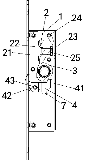
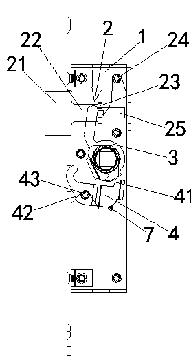
[0037] figure 1 It is a schematic structural diagram of the silent lock in the unlocked state according to this embodiment; figure 2 It is a structural schematic diagram of the silent lock in the locked state according to this embodiment.

[0038] This embodiment describes a silent lock, including a lock body and a lock plate, wherein the lock plate (not shown in the figure) is fixed on the door frame or window frame, and a cavity is opened on the lock plate. The structure of the lock plate can be Choosing a conventional structure is not the main point of the present invention, and will not be repeated here.

[0039] Such as figure 1 , figure 2 As shown, the lock body includes a lock box 1, a lock tongue assembly 2, a toggle block 3 and a handle (not shown in the figure). The lock tongue assembly 2 and the toggle block 3 are both located in the lock box 1, and the handle passes The square shaft drives the toggle block 3 to rotate, and the toggle block 3 then drives the lock tongu...

Embodiment 2

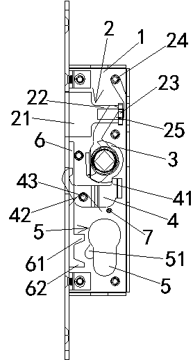
[0046] image 3 It is a schematic structural diagram of the silent lock according to this embodiment in an unlocked state, wherein a locking mechanism is provided in the lock box; Figure 4 It is a schematic structural diagram of the silent lock in the locked state according to this embodiment, in which a locking mechanism is provided in the lock box.

[0047] The main structure of the multiple silent lock described in this embodiment is basically the same as the silent lock structure described in the first embodiment. In this embodiment, the lock body is also provided with a locking mechanism 5 for locking the bolt 21. Such as image 3 , Figure 4 The locking mechanism 5 shown includes a shifting block 51, a shifting block driving mechanism 52, and a locking block 6. The shifting block driving mechanism 52 is driven by an external device, and the shifting block 51 follows the actions of the shifting block driving mechanism 52. While rotating, the shifting block 51 drives the lo...


PUM


Abstract

The invention relates to a silent lock which comprises a lock body and a lock catch plate. The lock body comprises a lock box, a spring bolt assembly, a toggle block and a handle. The handle is connected with the toggle block and can drive the toggle block to rotate, the toggle block is in linkage with the spring bolt assembly for driving the spring bolt assembly to stretch and retract, the lock catch plate is provided with a cavity for limiting a spring bolt, the lock body is further provided with a clamping block, and the clamping block can be rotationally fixed in the lock box. The silent lock has an unlocked state and a locked state. In the unlocked state, the front end of the spring bolt is located in the lock box, and the clamping block is clamped to the toggle block. In the locked state, the front end of the spring bolt protrudes out of the lock box, the clamping block is disengaged from the toggle block, and the clamping block is used for switching the locked state and the unlocked state of the silent lock. The spring bolt can be automatically sprung out while being locked, automatic locking is achieved, safety is improved, and silent locking and unlocking are achieved.

Description

Technical field [0001] The invention relates to a lock, in particular to a silent lock capable of automatically realizing contraction and locking of a bolt. Background technique [0002] When doors and windows are closed, people often forget to lock the doors and windows due to a momentary negligence or habit, which brings certain security risks. The doors and windows can be opened directly, and there is a possibility of theft. If the doors and windows can be automatically locked when the doors and windows are closed, it will undoubtedly greatly improve the safety. However, at present, only the structure of window closers and other structures can achieve the closing of doors and windows, and the automatic locking door locks have not been effectively and simply realized. [0003] Another is that when the door and window are closed, the bolt of the lock touches the lock plate, retracts inward, and then the lock tongue pops out and locks in the cavity in the lock plate to realize lock...

Claims


Application Information

Patent Timeline
Patent Type & Authority Applications(China)
IPC IPC(8): E05B17/00E05B15/00E05B63/18
CPCE05B15/00E05B17/0045E05B63/18
Inventor 朱力克聂飞
Owner JIANGSU QUNXIONG INTELLIGENT TECH
Why Eureka
Try Eureka