
Focusing lamp lens set and corresponding lighting system

A lamp lens and focusing technology, applied in the field of optics, can solve the problems of low light efficiency and low optical efficiency, achieve clear light spots, overcome light spot layering, and improve the effect of irradiation

Pending Publication Date: 2018-11-16
SELF ELECTRONICS CO LTD
View PDF6 Cites 5 Cited by
  • Summary
  • Abstract
  • Description
  • Claims
  • Application Information

AI Technical Summary

Problems solved by technology

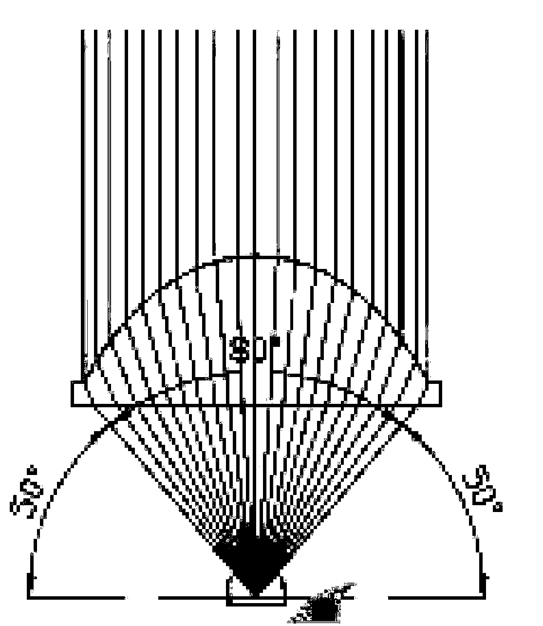
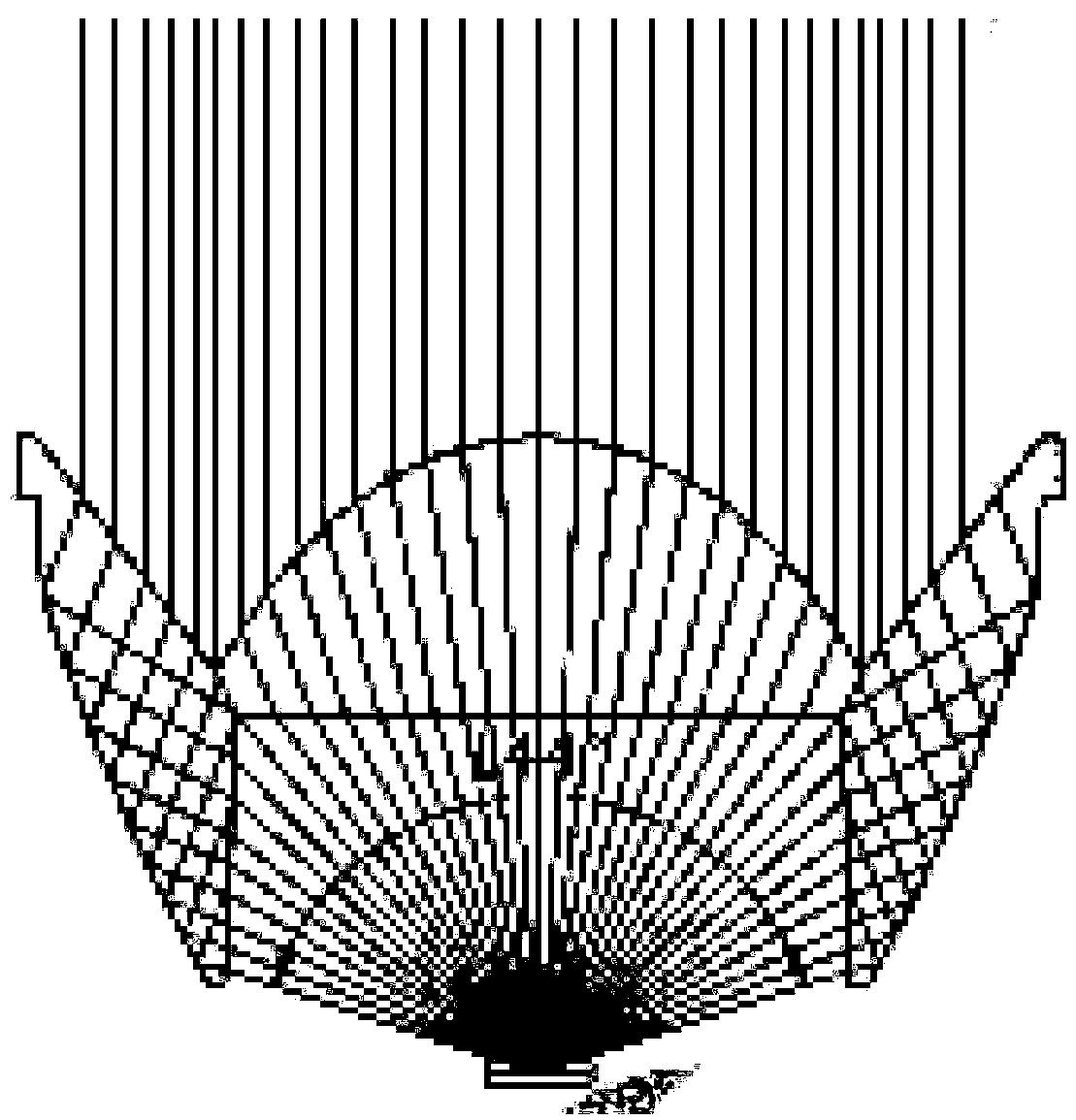
[0004] Among them, the single convex lens zoom lens shown in Figure 1(a) mainly realizes the change of the light emitting angle by adjusting the distance between the convex lens and the LED light source, and the light efficiency in this way is relatively low; the zoom collimator lens shown in Figure 1(b) Mainly by moving the convex lens close to the direction of the LED light to achieve the large-angle light demand, and through the cooperation of the total reflection surface and the convex lens to achieve the small-angle light demand, although this light distribution method has multiple adjustment capabilities and relatively high light efficiency, but in adjusting During the focusing process, it is easy to cause stratification of the illumination spot due to the inconsistent relationship between the convex lens and the total reflection surface with respect to the light source; the multi-lens combination shown in Figure 1(c) adjusts the light through a series of convex lenses and concave lenses. Although the light distribution method produces clear light spots and good illumination effects, the optical efficiency is low

Method used


Image

  • Focusing lamp lens set and corresponding lighting system
  • Focusing lamp lens set and corresponding lighting system
  • Focusing lamp lens set and corresponding lighting system

Examples


Embodiment Construction

[0018] Embodiments of the present invention are described in detail below, examples of which are shown in the drawings, wherein the same or similar reference numerals designate the same or similar elements or elements having the same or similar functions throughout. The embodiments described below by referring to the figures are exemplary only for explaining the present invention and should not be construed as limiting the present invention.

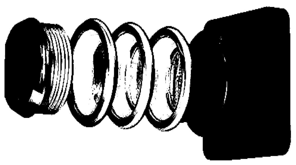
[0019] figure 2 , Figure 3(a)-3(d) The structure of an embodiment of the focusing lamp lens group of the present application and the corresponding lighting system are shown. The focusing lamp lens group of the present application includes a first lens that can emit all the light emitted by the light source, and a lens assembly that is located on the light-emitting side of the first lens and can obtain different light-emitting angles by adjusting the distance between its own internal components. The distance between a lens and the lig...


PUM


Abstract

The invention relates to a focusing lamp lens set. The focusing lamp lens set comprises a first lens and a lens assembly, wherein the space between the first lens and a light source is fixed, the first lens emits all lights of the light source, and the lens assembly is located on the light emitting side of the first lens; the lens assembly comprises one or more concave lenses and one or more convex lenses, wherein the convex lenses are located between the first lens and the concave lenses; the convex lenses and the concave lenses have the same radius and the same refractive index, the convex faces of the convex lenses are opposite to the concave faces of the concave lenses, and the space between the convex lenses and the concave lenses can be adjusted so that different emitting angles canbe obtained. By the adoption of the focusing lamp lens set, the light efficiency is improved, and the irradiation effect is good.

Description

technical field [0001] The invention relates to the field of optics, in particular to a focusing lamp lens group and a corresponding lighting system. Background technique [0002] With the application of LED lights more and more widely, higher requirements are put forward for LED lighting. For example, in shopping malls, counters and other occasions, lamps are required to have soft and smart light to avoid glare and prevent visual pressure on customers. In street lighting, especially in smoggy weather, it is hoped that the light emitted by the lamps can shine far enough and have enough penetrating power. [0003] As we all know, an important factor affecting the light effect is the angle of the outgoing light. In order to meet different light effect requirements, people try to improve the lighting effect by designing different zoom lamp lenses and changing the angle of the outgoing light. At present, the existing zoom lamp lenses mainly include three types: single convex le...

Claims


Application Information

Patent Timeline
Patent Type & Authority Applications(China)
IPC IPC(8): F21V5/04F21V5/00F21V7/00F21Y115/10
CPCF21V5/008F21V5/048F21V7/0091F21Y2115/10G02B19/0028G02B19/0061G02B7/10F21V14/06F21V5/045F21V5/046G02B15/142
Inventor 何祖平董建国杨君张发伟
Owner SELF ELECTRONICS CO LTD
Learn More