A highly angularly stable frequency selective surface

A frequency selective surface, high-angle technology, applied to antennas, electrical components, etc., can solve the problem of low angular stability, and achieve the effect of reducing offset, reducing unit size, and improving angular stability characteristics

Active Publication Date: 2019-11-15
XIDIAN UNIV +1
View PDF9 Cites 0 Cited by
  • Summary
  • Abstract
  • Description
  • Claims
  • Application Information

AI Technical Summary

Problems solved by technology

[0004] The purpose of the present invention is to overcome the defects in the above-mentioned prior art, and propose a frequency selective surface with high angular stability, which is used to solve the technical problem of low angular stability existing in the existing frequency selective surface

Method used


Image

  • A highly angularly stable frequency selective surface
  • A highly angularly stable frequency selective surface
  • A highly angularly stable frequency selective surface

Examples


Embodiment 1

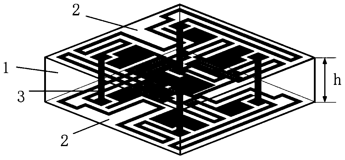
[0029] refer to figure 1 , a frequency selective surface unit with high angle stability, the frequency selective surface unit includes a dielectric substrate 1 , metal patches 2 printed on the upper and lower surfaces of the dielectric substrate 1 , and metallized via holes 3 .

[0030] The dielectric substrate 1 adopts a square plate with a relative permittivity of 2.2, its side length is t=6.7mm, and its thickness is h=1.6mm.

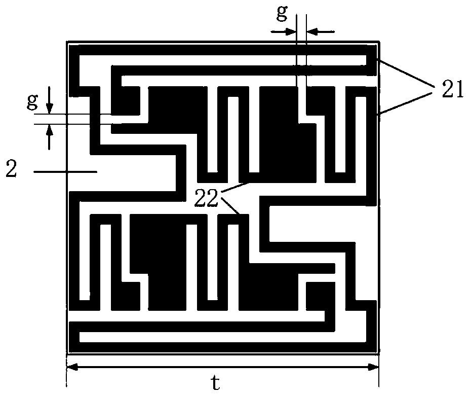
[0031] The pair of metal rings on the lower surface of the dielectric substrate 1 is located at a position where the projection of the pair of metal rings on the upper surface is rotated by 90 degrees on the lower surface, and the opening ends of the pair of split metal rings on the upper surface are aligned with the pair of metal rings on the lower surface. The corresponding positions of the open ends of the split metal ring pair are connected through the metallized via hole 3, and the connection line between the corresponding ports of the split meta...

Embodiment 2

[0045] The structure of this embodiment is the same as that of Embodiment 1, and only the following parameters have been adjusted:

[0046] The dielectric substrate 1 adopts a relative permittivity of 4.4, a length of t=8mm, a thickness of h=3mm, a length of the metal patch a of 7.9mm, a line width of w=0.1mm, g=0.1mm, r=0.25mm.

Embodiment 3

[0048] The structure of this embodiment is the same as that of Embodiment 1, and only the following parameters have been adjusted:

[0049] The dielectric substrate 1 adopts a relative dielectric constant of 4.4, a length of t=6mm, a thickness of h=3mm, a length of the metal patch a of 5.9mm, a line width of w=0.3mm, g=0.3mm, r=0.1mm.

[0050] Below by simulation experiment, the technical effect of the present invention is described further:

[0051] 1. Simulation conditions and simulation content:

[0052] The simulation utilizes the commercial software HFSS_15.0.

[0053] Simulation 1, the transmission coefficient curve of the TE wave in the embodiment 1 of the present invention is simulated from the incidence angle 0 ° ~ 87 °, and the results are as follows Figure 7 shown.

[0054] Simulation 2, the TM wave in the embodiment of the present invention 1 is simulated from the transmission coefficient curve of the incident angle 0 ° ~ 87 °, the result is as follows Figure...


PUM


Abstract

The invention provides a frequency selective surface with high angular stability, and is used for solving the problem of relatively low angular stability existing in the prior art. The frequency selective surface comprises M*N frequency selective surface units arranged periodically; each frequency selective surface unit comprises a dielectric plate, and a metal ring pair consisting of two oppositely arranged opening metal rings and a metal patch pair consisting of two oppositely arranged opening metal patches on the upper surface and the lower surface of the dielectric plate; the two metal rings on the same surface are opposite in opening directions; first rectangular grooves in the two metal patches are opposite in directions, and are of 180-degree rotational symmetry about the normal line of the dielectric plate; the position of the metal ring pair corresponds to the position the metal patch pair on the same surface; the projections, on the lower surface of dielectric plate, of the metal ring pair positioned on the lower surface of the dielectric plate and the metal ring pair positioned on the upper surface of the dielectric plate rotate by 90 degrees, metal via holes are used for correspondingly and vertically connecting the opening ends of the two metal ring pairs so as to form the 2.5D frequency selective surface unit structure with high angular stability.

Description

technical field [0001] The invention belongs to the technical field of electromagnetic fields and microwaves, and in particular relates to a frequency selective surface with high angular stability, which can be used in many scenes that have strict requirements on the angular stability of the frequency selective surface, such as reflector antennas. Background technique [0002] Frequency Selective Surface FSS (Frequency Selective Surface) is a two-dimensional periodic structure composed of periodic arrangements of resonant units. According to the structure of the unit, the frequency selective surface can be divided into patch type and aperture type. The patch type frequency selective surface mostly shows band-stop characteristics, and the aperture type frequency selective surface mostly shows bandpass characteristics. These characteristics make frequency selective surfaces widely used in civilian fields such as spatial filters and antenna reflectors. When the frequency selec...

Claims


Application Information

Patent Timeline
Patent Type & Authority Patents(China)
IPC IPC(8): H01Q15/00
CPCH01Q15/0013
Inventor 姜文陈帅崔阳强洪涛龚书喜
Owner XIDIAN UNIV
Why Eureka
Try Eureka