
An ultra-wideband planar helical antenna loaded with a dielectric lens

A flat helix, dielectric lens technology, applied in the directions of antenna arrays, antennas, electrical components, etc., which are energized separately, can solve the problems of narrowing of the working frequency band of the antenna, deterioration of the antenna performance, insufficient working bandwidth, etc., and achieve good radiation performance and simple structure. Lightweight, high-gain effects

Active Publication Date: 2022-07-12
南京软赫电子科技有限公司 +1
View PDF7 Cites 0 Cited by
  • Summary
  • Abstract
  • Description
  • Claims
  • Application Information

AI Technical Summary

Problems solved by technology

The planar helical antenna has the characteristics of wide frequency band and small size, but because its radiated energy is bidirectional, in order to obtain unidirectional radiation characteristics, people usually load a reflective cavity on the back, but because the reflective cavity is a resonant device, it will inevitably lead to antenna The working frequency band is narrowed, coupled with the reflection from the side wall of the reflective cavity, the performance of the antenna will deteriorate sharply
[0004] The patent with the application number "201620619384.X" discloses a broadband miniaturized antenna for 5G mobile communications, including a metal patch, a helical antenna element, a broadband balun, a trapezoidal horn, a ring, and a reflection ground. There are good electrical characteristics in the 3-6GHz frequency range, but the half-power (-3dB) opening angle of the antenna is about 100°, which is too wide, resulting in a small antenna gain, and its working bandwidth is far away in the application fields such as breast cancer detection. insufficient

Method used


Image

  • An ultra-wideband planar helical antenna loaded with a dielectric lens
  • An ultra-wideband planar helical antenna loaded with a dielectric lens
  • An ultra-wideband planar helical antenna loaded with a dielectric lens

Examples


Embodiment Construction

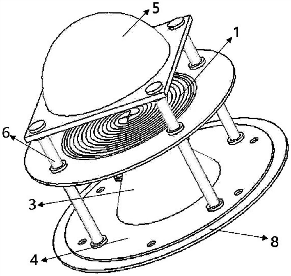
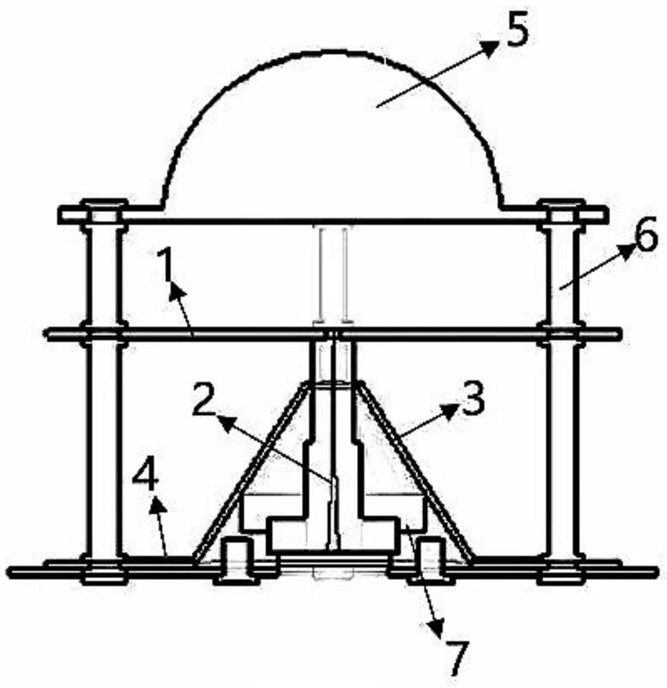
[0037] like Figure 1-2 As shown in the figure, the present invention discloses an ultra-wideband planar helical antenna loaded with a dielectric lens, including a circular reflective bottom plate 4, a circular frustum-shaped metal reflective backplane 3, a planar helical antenna radiation structure 1 and a hemisphere sequentially arranged from bottom to top The bulk dielectric lens 5 and the microstrip balun feeding structure 2 are arranged inside the truncated metal reflective backplane 3 , and the planar helical antenna radiating structure 1 is fed through the microstrip balun feeding structure 2 .

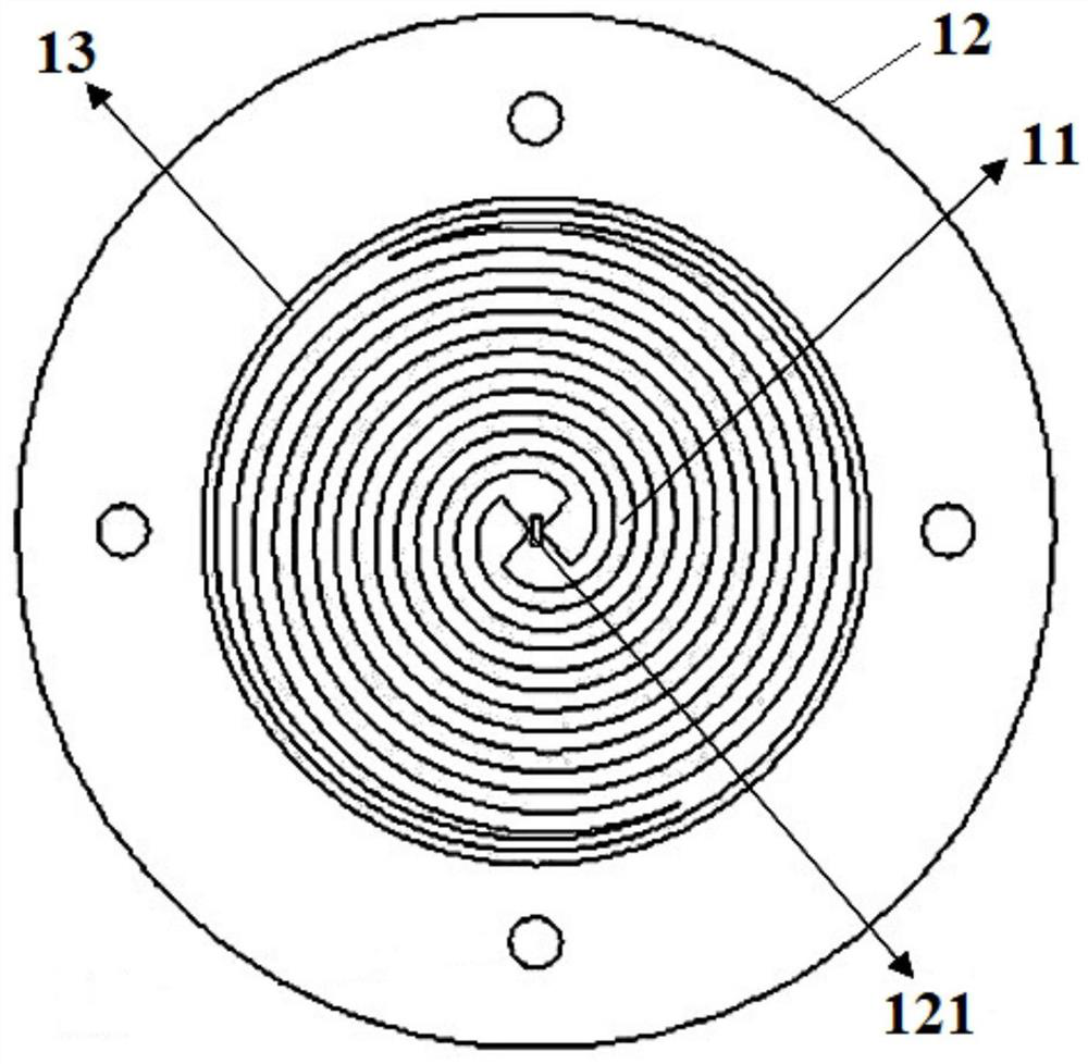
[0038] like image 3 As shown, the planar helical antenna radiation structure 1 includes an Archimedes helix 11, a planar helical antenna dielectric substrate 12 and a metal ring 13, and the Archimedes helix 11 and the metal ring 13 are both arranged on the planar helical antenna dielectric substrate 12 , the Archimedes spiral 11 includes two radiating arms that are rotational...


PUM

PropertyMeasurementUnit
radiusaaaaaaaaaa
radiusaaaaaaaaaa
thicknessaaaaaaaaaa

Abstract

The invention relates to the technical field of microwaves and antennas, in particular to an ultra-wideband planar helical antenna loaded with a dielectric lens, comprising a circular reflective bottom plate, a circular frustum-shaped metal reflective backplane, a planar helical antenna radiation structure and The hemispherical dielectric lens, the microstrip balun feeding structure is arranged inside the truncated metal reflective backplane, and the plane helical antenna radiation structure is fed through the microstrip balun feeding structure. The purpose of the present invention is to meet the requirements of high-gain and wide-band antennas in medical fields such as breast cancer detection and imaging, and propose a structure in which a dielectric lens and a truncated reflective backplane are loaded on the basis of the Archimedes helical antenna. It can solve the technical problem that the planar helical antenna cannot have miniaturization, ultra-wideband and good radiation performance at the same time.

Description

technical field [0001] The invention relates to the technical field of microwaves and antennas, in particular to an ultra-wideband planar helical antenna loaded with a dielectric lens. Background technique [0002] With the rapid development of modern communication technology, people have put forward higher requirements for high-speed wireless communication, the radio frequency spectrum has been continuously expanded, and the communication bandwidth requirements have also been broadened. As an important device for radiating and receiving electromagnetic waves, antennas are an important part of radio systems. With the emergence of ultra-wideband systems, the research on ultra-wideband (UWB) antennas has become an important branch in the field of antennas. Not only that, ultra-wideband antennas with broadband performance, high gain, and miniaturization have received more and more attention in FM broadcasting, satellite communications, radar, medical detection, imaging and othe...

Claims


Application Information

Patent Timeline
Patent Type & Authority Patents(China)
IPC IPC(8): H01Q19/06H01Q19/10H01Q21/06H01Q1/38
CPCH01Q19/06H01Q19/10H01Q21/06H01Q1/38
Inventor 梁志毅徐文虎王正斌
Owner 南京软赫电子科技有限公司
Learn More