Subband filter method based on subband filtering OFDM system

A subband filtering and filter technology, applied in baseband systems, baseband system components, modulated carrier systems, etc., can solve the problem of subband filter time-domain impulse response tailing, larger transition area, and wider roll-off bandwidth. and other problems to achieve the effect of saving frequency band resources, small signal delay, and avoiding influence

Inactive Publication Date: 2018-11-16
SHANGHAI INST OF MICROSYSTEM & INFORMATION TECH CHINESE ACAD OF SCI +1
View PDF4 Cites 4 Cited by
  • Summary
  • Abstract
  • Description
  • Claims
  • Application Information

AI Technical Summary

Problems solved by technology

The reserved frequency band is generally set to 2 to 12 subcarriers. If the setting is too small, the influence of the passband ripple of the subband filter on the edge subcarriers cannot be completely avoided. If the setting is too large, the passband of the subband filter will be cut off. The transition region at the frequency to the desired stopband attenuation becomes larger, that is, the equivalent transition band becomes wider
And for the linear phase filter designed by the soft truncated Sinc function method, the passband edge directly transitions from 1 to 0, resulting in serious smearing of the time domain impulse response of the subband filter and large passband ripples
[0010] For the soft truncated raised cosine sub-band filter, the roll-off bandwidth of the linear phase filter is a function of the roll-off coefficient and the sub-band bandwidth, and different users or different services of the same user have different sub-band bandwidths. , the roll-off coefficient needs to be reset, and at this time the passband edge of the linear phase filter slowly transitions from 1 to 0, the roll-off bandwidth is too wide and difficult to control, making the transition bandwidth of the RC-Filter wider

Method used


Image

  • Subband filter method based on subband filtering OFDM system
  • Subband filter method based on subband filtering OFDM system
  • Subband filter method based on subband filtering OFDM system

Examples


Embodiment Construction

[0031] Below in conjunction with specific embodiment, further illustrate the present invention. It should be understood that these examples are only used to illustrate the present invention and are not intended to limit the scope of the present invention. In addition, it should be understood that after reading the teachings of the present invention, those skilled in the art can make various changes or modifications to the present invention, and these equivalent forms also fall within the scope defined by the appended claims of the present application.

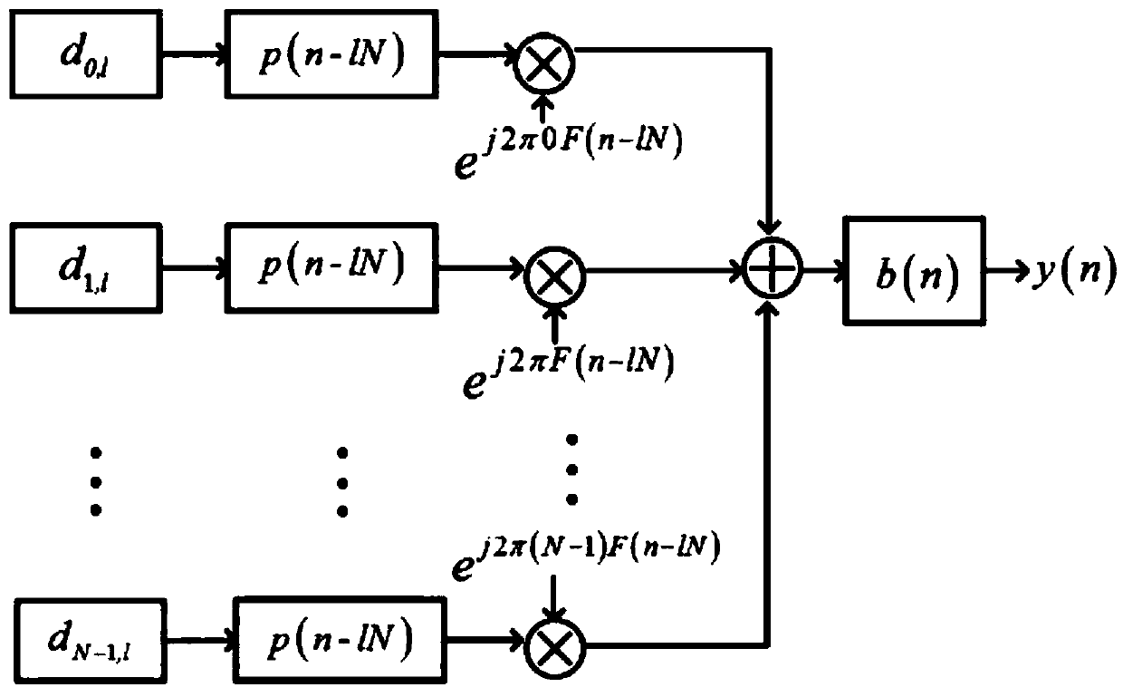
[0032] Embodiments of the present invention relate to a method for generating a subband filter based on a subband filtering OFDM system, comprising the following steps:

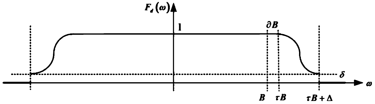
[0033] (1) First design a linear phase filter that satisfies the target frequency response, see the formula

[0034]

[0035] Among them, B is the sub-band bandwidth, τ is the reserved frequency band factor, δ is the roll-off cut-off amplitude, α is the ro...


PUM


Abstract

The invention relates to a subband filter method based on a subband filtering OFDM system. The method comprises the following steps: designing a linear phase filter meeting target frequency response and with a passband edge falling from 1 to a roll-off cut-off amplitude delta, the roll-off cut-off amplitude delta and a roll-off band width being controlled by a roll-off band factor; taking a roll-off function of the linear phase filter as a raised cosine function; selecting a window function; performing soft cutting off on the designed linear phase filter by the selected window function to generate the subband filter. The subband filter designed by the invention is large in stopband attenuation, small in passband ripple coefficient, small in time domain impulse response tail and narrow in transition band.

Description

technical field [0001] The present invention relates to the technical field of sub-band filters, in particular to a sub-band filter design method based on a sub-band filtering OFDM system. Background technique [0002] The existing 5G new waveform design is generally based on the OFDM multi-carrier modulation system, see figure 1 . There are currently two design angles: the first is the reshaping pulse shaping filter method, which improves p(n), that is, performs pulse shaping on each subcarrier in the frequency domain, and FBMC and WOLA belong to this category ; The second is to add a bandpass filter method, that is, carry out frequency domain bandpass windowing processing on a continuous subcarrier, subband filtering (abbreviated as "filtered") OFDM (FOFDM, RB-FOFDM), UFMC, FCP- OFDM falls into this category. [0003] FBMC filters a single subcarrier, so the time-domain impulse response of the filter has a large tail, and does not support 5G low-latency services and sma...

Claims


Application Information

Patent Timeline
Patent Type & Authority Applications(China)
IPC IPC(8): H04L27/26H04L25/03H04L5/00
CPCH04L5/0008H04L25/03012H04L27/2601H04L27/264
Inventor 李颖锐易辉跃徐景舒睿俊杨旸
Owner SHANGHAI INST OF MICROSYSTEM & INFORMATION TECH CHINESE ACAD OF SCI
Why Eureka
Try Eureka