

Knitwear dust removing and ironing device
A technology for knitwear and dust, which is applied in the field of knitwear dust cleaning and ironing devices, and can solve problems affecting the quality of knitwear, knitwear fading, etc.
- Summary
- Abstract
- Description
- Claims
- Application Information
AI Technical Summary
Problems solved by technology
Method used
Image

Examples
Embodiment 1
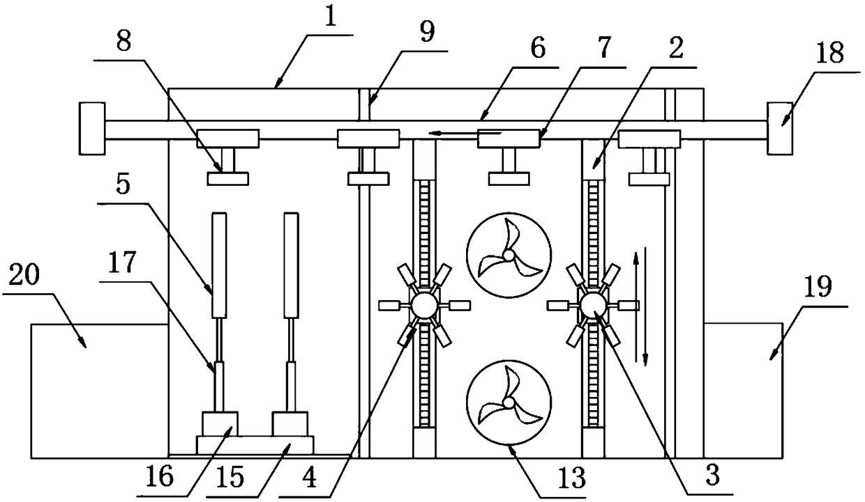
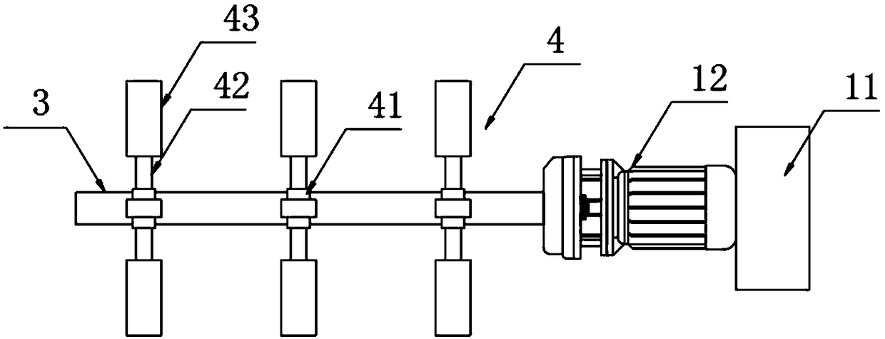
[0021] according to Figure 1-3 The shown dust cleaning and ironing device for knitwear includes a device main body 1, two sets of upper and lower guide rails 2 are arranged on both sides of the inner wall of the device main body 1, and a rotating shaft 3 is arranged between the upper and lower guide rails 2 on both sides. A plurality of ash-beating devices 4 are set on the rotating shaft 3, two groups of irons 5 are arranged on one side of the ash-beating device 4, and left and right guide rails 6 are arranged on the top of the ash-beating device 4, and the two ends of the left and right guide rails 6 respectively pass through The two side walls of the equipment main body 1 extend to one side of the outer wall of the equipment main body 1. The bottom of the left and right guide rails 6 is movably engaged with multiple sets of first stepping motors 7, and the bottom of the first stepping motors 7 is fixedly provided with a clothes hanger 8. Dust-proof doors 9 are arranged on b...
Embodiment 2
[0024] The difference with embodiment 1 is:
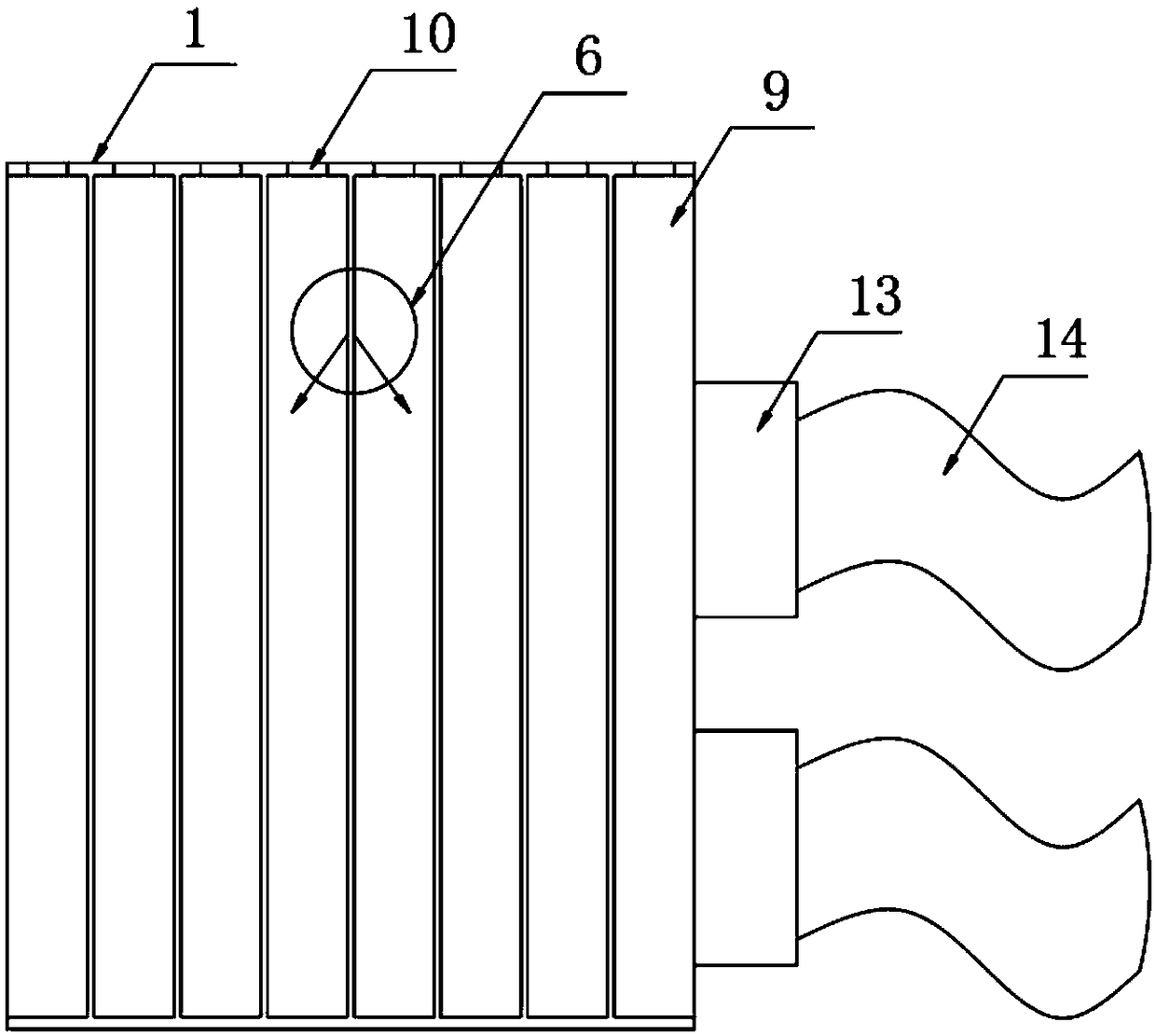
[0025] The dust-proof door 9 is provided with a plurality, and the top of the plurality of dust-proof doors 9 is fixedly provided with a connecting rod 10, and the top of the connecting rod 10 is fixedly connected with the top wall of the equipment main body 1, and the plurality of dust-proof doors 9 They fit each other, and the dust-proof door 9 is made of elastic rubber, which helps to isolate the dust being cleaned and the knitwear that has been dusted, and prevents the clean knitwear from absorbing dust again.
[0026] A rotating motor 11 is movably clamped on the upper and lower guide rails 2 , and a second stepping motor 12 is fixedly arranged on one side of the rotating motor 11 , and the output end of the second stepping motor 12 is connected to the input end of the rotating shaft 3 .
[0027] One side of the device main body 1 is provided with a fan 13 at the upper and lower ends, one end of the fan 13 runs through the sid...
PUM
 Abstract
Description
Claims
Application Information