Assembled concrete bridge pier

A prefabricated, concrete technology, applied in the direction of bridges, bridge parts, bridge construction, etc., can solve the problems of shock absorption, poor seismic performance, difficult assembly, and time-consuming, etc., and achieve the effect of enhanced seismic resistance and efficient, convenient and fast assembly.

Active Publication Date: 2018-11-20
河南晟源路桥工程管理有限公司
View PDF7 Cites 14 Cited by
  • Summary
  • Abstract
  • Description
  • Claims
  • Application Information

AI Technical Summary

Problems solved by technology

[0004] In view of the above problems, the present invention provides a prefabricated concrete pier, which effectively solves the problems in the prior art that the assembly between the prefabricated concrete pier and the prefabricated cap beam is difficult, takes a long time, and has poor shock absorption and anti-seismic performance.

Method used


Image

  • Assembled concrete bridge pier
  • Assembled concrete bridge pier
  • Assembled concrete bridge pier

Examples


Embodiment 1

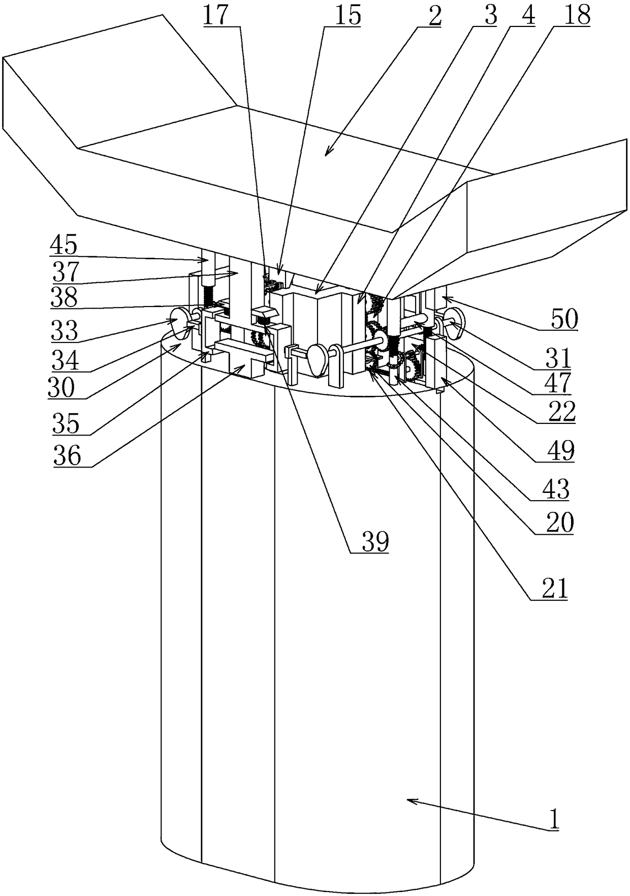
[0027] Embodiment one, combined with the attached Figure 1-9 , prefabricated concrete pier 1, including pier 1 and precast concrete cover beam 2, pier 1 and concrete cover girder 2 need to be assembled, pier 1 and prefabricated concrete cover girder 2 are prefabricated in advance, realizing the three-dimensional intersection operation , which ensures green construction and saves a lot of construction time. It is characterized in that the upper end of the bridge pier 1 is connected with a square support platform 3 opening upwards. Well, in preparation for the assembly with the cover beam 2, two sets of support plates 4 vertically parallel and symmetrically arranged are respectively connected to the outer walls around the support platform 3, and two sets of support plates 4 are respectively arranged on the inner walls around the support platform 3. A group of symmetrically arranged rectangular slideways 5, preferably, the position of the rectangular slideway 5 is selected as fa...

Embodiment 2

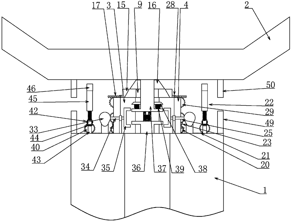
[0031] Embodiment two, on the basis of embodiment one, in conjunction with the attached Figure 1-9 , the transmission device 18 includes a first gear 23 placed above the drive gear 20 and rotatably connected between the two support plates 4, combined with the attached Figure 8 , the first gear 23 meshes with the driving gear 20, the driving gear 20 is driven by the rotation of the rotating plate 12, and the upper end of the first gear 23 is meshed with a second gear that is rotatably connected between the two supporting plates 4 24, the two sides of the second gear 24 are coaxially connected with a third gear 25 placed between the two support plates 4, the radius of the second gear 24 is smaller than the radius of the third gear 25, where the second gear 24 and The 3rd gear 25 not only plays the seat of transmission, also plays the effect of amplifying the stroke, expands the rotation stroke that drive gear 20 transmits, makes the stroke of its output larger, also includes o...

Embodiment 3

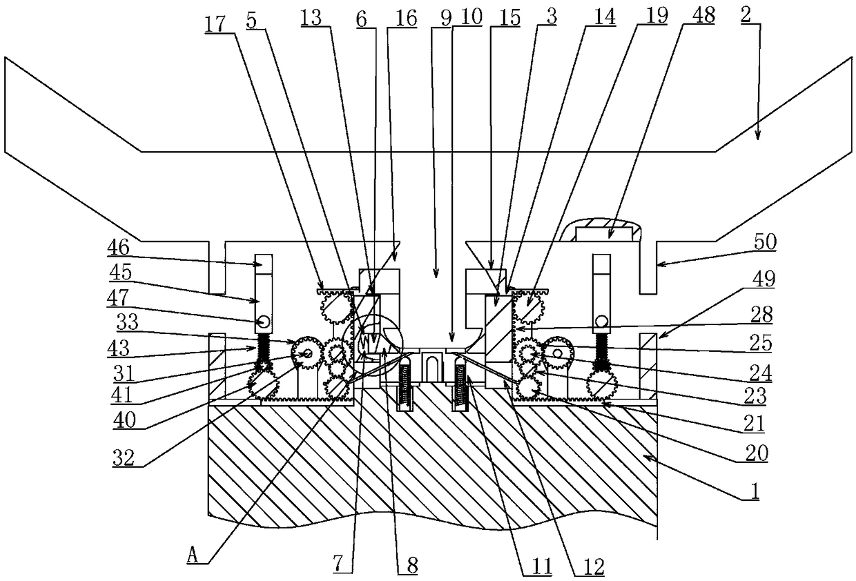
[0033] Embodiment three, on the basis of embodiment two, in conjunction with appended Figure 1-9 The vertical displacement limiting device 30 includes a rotating shaft 31 that is rotatably connected to the upper end of the pier 1 and extends along the front and rear directions. The rotating shaft 31 is coaxially connected with two sets of fifth gears 32, and the two sets of fifth gears 32 are respectively connected The two groups of third gears 25 on the same side mesh, and the fifth gear 32 is driven by the third gear 25 to provide power input for the rotating shaft 31,

[0034] The front and rear side shaft ends of the rotating shaft 31 are respectively coaxially connected with cams 33, combined with the attached Image 6 , the direction of the protruding end of the cam 33 should be set downwards, the cams 33 are respectively placed in the direction of the front and rear sides of the support platform 3, and the cam 33 is provided with a horizontal sliding connection in the ...


PUM


Abstract

The invention relates to an assembled concrete bridge pier. When a cover beam is assembled with the assembled concrete bridge pier, positioning is carried out through a first magnetic rod and a secondmagnetic rod generally; along with descending of the cover beam, a clamping block is matched with a curved surface ring, and displacement of a circular column in a vertical direction is limited; along with extrusion of an elastic column pin, a rotating plate is driven by the circular column to drive a driving gear to rotate, then a right angle inverted trapezoidal block is matched with an inclined surface ring, the circular column is tightly clamped in a horizontal direction, the cover beam can be very well positioned, displacement of the cover beam in a horizontal direction and a vertical direction can be also limited, and a very good effect in resisting earthquake of different grades can be achieved; while the cover beam descends, a horizontal displacement limiting device and a verticaldisplacement limiting device can be also driven by the driving gear, the cover beam can be further limited in the horizontal direction and the vertical direction after being assembled and positioned,the overall earthquake resistance and reduction effect can be improved, and the assembled concrete bridge pier is efficient, convenient and rapid to assemble, and has very good earthquake resistanceand reduction effects.

Description

technical field [0001] The invention belongs to the technical field of concrete bridge piers, in particular to an assembled concrete bridge piers. Background technique [0002] The prefabricated concrete structure is a concrete structure that is assembled and connected with prefabricated components as the main force-bearing components. Prefabricated reinforced concrete structure is one of the important directions for the development of my country's building structure. It is conducive to the development of my country's building industrialization, improving production efficiency and saving energy, developing green and environmentally friendly buildings, and is conducive to improving and ensuring the quality of construction projects. Compared with the cast-in-place construction method, the prefabricated PC structure is conducive to green construction, because the prefabricated construction can better meet the requirements of green construction, such as land saving, energy savin...

Claims


Application Information

Patent Timeline
Patent Type & Authority Applications(China)
IPC IPC(8): E01D19/02E01D19/04
Inventor 梁胜军王德敏孙浩张彩霞姬红光刘全明杨建昌朱振刘海峰王玉琴王红阳梁爽王文龙杜龙陈刚张凯
Owner 河南晟源路桥工程管理有限公司
Why Eureka
Try Eureka