
Mechanical pressurized air-feeding equipment

An air supply equipment and mechanical pressurization technology, applied in mechanical equipment, liquid variable capacity machinery, machines/engines, etc., can solve the problems of not being able to meet the needs of fire protection, weak wind power, etc., and achieve simple structure, strong wind power, Suitable for large-scale promotion

Inactive Publication Date: 2018-11-20
刘佩玲
View PDF6 Cites 2 Cited by
  • Summary
  • Abstract
  • Description
  • Claims
  • Application Information

AI Technical Summary

Problems solved by technology

Moreover, due to the reduction of complex structures, the overall appearance of the fan is more concise and beautiful, but the structure of the air supply device is simple, and the wind delivered is weak, which cannot meet the needs of fire protection

Method used


Image

  • Mechanical pressurized air-feeding equipment
  • Mechanical pressurized air-feeding equipment
  • Mechanical pressurized air-feeding equipment

Examples


Embodiment

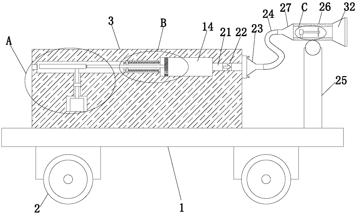
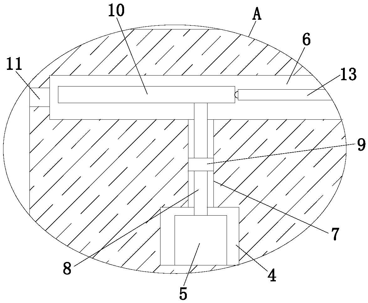
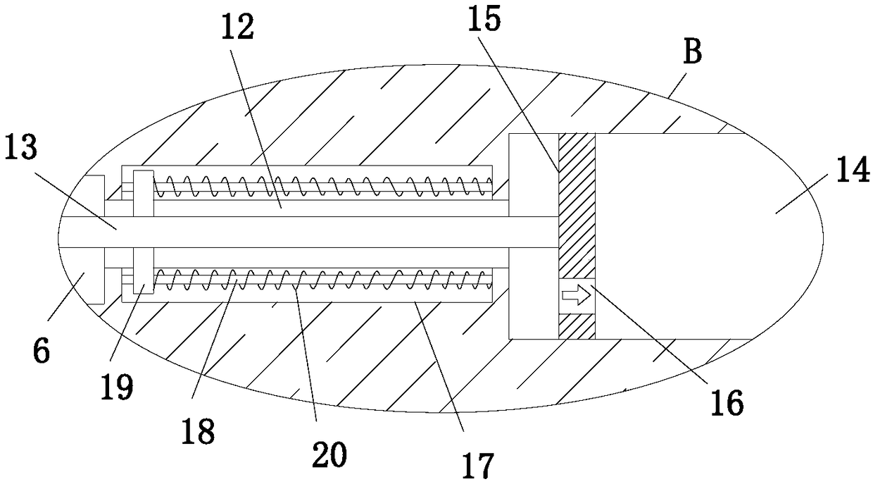
[0025] refer to Figure 1-5 In this embodiment, a mechanically pressurized air supply device is proposed, including a base 1, a plurality of rollers 2 are installed on the bottom side of the base 1, a mounting base 3 is fixedly installed on the top side of the base 1, and a mounting base 3 is provided on the mounting base 3. Motor chamber 4, the first motor 5 is fixedly installed in the motor chamber 4, the mounting base 3 is provided with a cavity 6, the cavity 6 is located above the motor chamber 4, and a through hole 7 is provided on the inner wall of the top side of the motor chamber 4, A rotating shaft 8 is installed in the through hole 7, the bottom end of the rotating shaft 8 extends into the motor cavity 4 and is fixedly connected with the output shaft of the first motor 5, and the top end of the rotating shaft 8 extends into the cavity 6 and a cam 10 is fixedly installed. A pressurized cavity 14 is opened on the base 1, and the pressurized cavity 14 is located on one ...


PUM


Abstract

The invention discloses mechanical pressurized air-feeding equipment. The mechanical pressurized air-feeding equipment comprises a base, wherein the bottom side of the base is equipped with a plurality of rollers; the top side of the base is fixedly equipped with a mounting base; a motor cavity is arranged on the mounting base; a first motor is fixedly mounted in the motor cavity; a cavity is arranged on the mounting base; the cavity is positioned above the motor cavity; a through hole is formed in the inner wall of the top side of the motor cavity; a rotary shaft is rotatably mounted in the through hole; the bottom end of the rotary shaft extends into the motor cavity and is fixedly connected with the output shaft of the first motor; the top end of the rotary shaft extends into the cavityand is fixedly equipped with a cam; a pressurizing cavity is arranged on the base; the pressurizing cavity is positioned at one side of the cavity; a through hole is formed in the inner wall, close to one side of the cavity, of the pressurizing cavity; the through hole communicates with the cavity; and a slide rod is mounted in the through hole in a sliding mode. Air power of air conveyed by themechanical pressurized air-feeding equipment is relatively strong, so that fire-fighting needs can be met. The mechanical pressurized air-feeding equipment is simple in structure, is low in manufacturing cost, and is suitable for large-scale popularization.

Description

technical field [0001] The invention relates to the technical field of air supply equipment, in particular to a mechanically pressurized air supply equipment. Background technique [0002] At present, in fire safety, it is necessary to carry out air supply treatment when a fire occurs, and an air supply device needs to be used. [0003] Patent No. 201320468681.5, an invention patent for a self-cooling device for a mixed-flow pressurized blower, discloses a pressurized air supply device, including an outer barrel, an inner barrel arranged inside the outer barrel, a motor arranged inside the inner barrel, The impeller driven by the motor; one end of the inner bucket has a cover plate, and the other end is provided with a vent, and the cover plate is provided with an air induction hole. The present invention saves the air induction pipe in the prior art, thus saving the corresponding time of welding, grinding, etc., as well as the loss of materials and manpower. In the past, ...

Claims


Application Information

Patent Timeline
Patent Type & Authority Applications(China)
IPC IPC(8): F04B35/04F04B39/00F04B39/10F04B41/06F04D25/08
CPCF04B35/04F04B39/00F04B39/10F04B41/06F04D25/08
Inventor 刘佩玲
Owner 刘佩玲
Learn More