Counter rotating fan

A rotary fan and impeller rotation technology, applied in the field of counter-rotating fans, can solve the problems of rising blade frequency and blade frequency multiplier noise peak, declining aerodynamic performance and noise performance, unfavorable motor heat dissipation, etc., to achieve critical speed increase and speed distribution. , to ensure the effect of fan performance

Active Publication Date: 2020-04-21
GUANGDONG MIDEA WHITE HOME APPLIANCE TECH INNOVATION CENT CO LTD +1
View PDF11 Cites 8 Cited by
  • Summary
  • Abstract
  • Description
  • Claims
  • Application Information

AI Technical Summary

Problems solved by technology

[0004] When the length of a single blade of the fan is long, the adjustment of the rotation speed is limited, otherwise the blade deformation will be large, and the aerodynamic performance and noise performance will be reduced. Although the use of harder blades can solve the problem of blade deformation, the cost is higher
At this time, if the fan is a long-blade type with a relatively small hub, the root of the blade will have a large twist, and the root of the two-stage blade will produce a recirculation zone, the wind speed is low and the wind will not blow forward, which is not conducive to the heat dissipation of the motor and affects the life of the motor.
[0005] For the sake of aesthetics, the overall design of the axial flow fan should not be too thick, otherwise it will seriously affect the appearance, and when the distance between the two-stage fans is small, the airflow such as the leakage vortex generated by the front-stage fan blades will easily enter the rear-stage fan blades, resulting in The noise peaks of frequency and leaf octave increase obviously, and the noise is larger

Method used


Image

  • Counter rotating fan
  • Counter rotating fan
  • Counter rotating fan

Examples


Embodiment Construction

[0035] Embodiments of the present invention are described in detail below, examples of which are shown in the drawings, wherein the same or similar reference numerals designate the same or similar elements or elements having the same or similar functions throughout. The embodiments described below by referring to the figures are exemplary only for explaining the present invention and should not be construed as limiting the present invention.

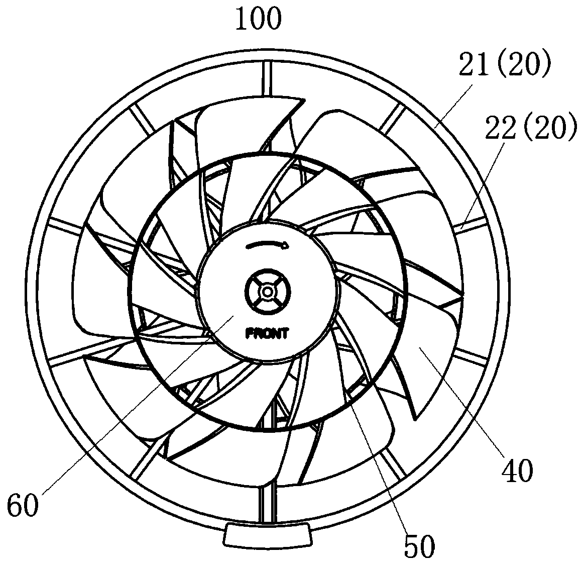
[0036] Refer below Figure 1-Figure 7 The counter-rotating fan 100 of the embodiment of the present invention will be described.

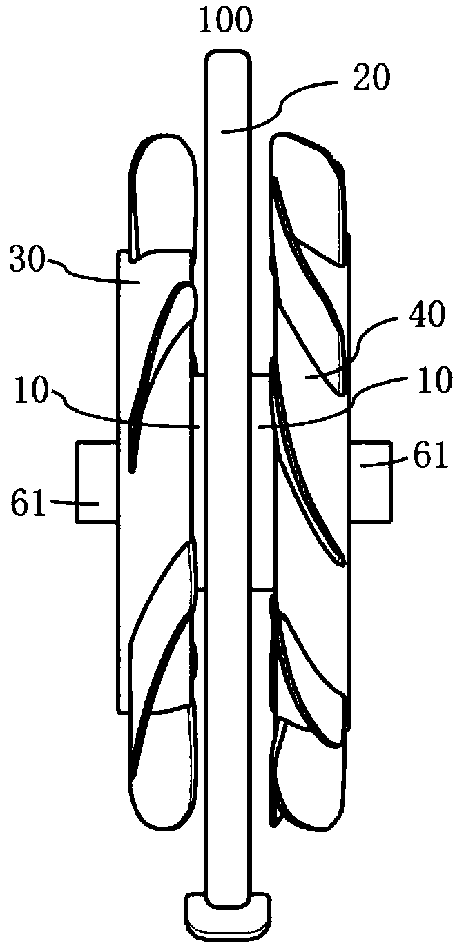
[0037] A counter-rotating fan 100 according to an embodiment of the present invention, such as figure 1 , figure 2 As shown, it includes: two impellers and a motor 10. Wherein, the motor 10 is used to drive the rotation of the two impellers to provide power for the rotation of the two-stage impellers.

[0038] The two impellers are spaced apart in the axial direction, namely the first-stage impeller 30 a...


PUM


Abstract

The invention discloses a counter rotating fan. The counter rotating fan comprises two impellers and a motor, the motor is used for driving the two impellers to rotate, the two impellers are arrangedat interval in the axial direction and divided into the first-stage impeller and the second-stage impeller, during running of the counter rotating fan, the air flow is blown from the first-stage impeller to the second-stage impeller, a plurality of rings of vanes are arranged on at least one of the impellers and distributed in the radial direction of the corresponding impeller, the multi vanes ofeach ring are arranged at intervals by surrounding the hub of the corresponding impeller, and a partition ring is connected between the two adjacent rings of vanes. According to the counter rotating fan, the impeller with the multi-ring vanes is adopted, the air output capacity in the middle of the counter rotating fan can be improved, the speed distribution near the center of the outlet wind field of the counter rotating fan is improved, and the uniformity of the outlet wind field is obviously improved.

Description

technical field [0001] The invention belongs to the technical field of fans, in particular to a counter-rotating fan. Background technique [0002] Fans can speed up the transmission of airflow, increase the air supply area to achieve wide-spread wind, or increase the wind stroke and air supply distance, speed up the wind speed and increase the convection speed, and are indispensable components in various household appliances. [0003] In the existing series-type two-stage axial fan, the two-stage fans have the same size and the same or opposite directions. The two-stage fans are respectively equipped with one motor or two motors to drive and rotate, and most of the rectification devices are arranged in the middle of the two-stage fans. The structure is relatively complex and the noise is large. When the two-stage fans rotate in different directions, the swirling airflow at the outlet of the first-stage fan can be de-rotated by the second-stage fan blades, and the straight ...

Claims


Application Information

Patent Timeline
Patent Type & Authority Applications(China)
IPC IPC(8): F04D25/08F04D25/16F04D29/32F04D29/58
CPCF04D25/08F04D25/166F04D25/163F04D29/325F04D29/5806F04D19/024F04D19/022F04D29/326F04D19/02F04D29/32F04D25/16F04D25/0606F04D29/582F05D2210/12F04D25/06
Inventor 胡小文胡斯特张辉易榕
Owner GUANGDONG MIDEA WHITE HOME APPLIANCE TECH INNOVATION CENT CO LTD
Why Eureka
Try Eureka