Rotatable tray type cable bridge

A cable tray and tray-type technology, applied in the direction of electrical components, etc., can solve the problems of cumbersome transportation and inflexible installation, and achieve the effects of flexible connection, effective heat dissipation, and avoiding heat accumulation

Inactive Publication Date: 2018-11-20
镇江宝源电仪设备有限公司
View PDF6 Cites 5 Cited by
  • Summary
  • Abstract
  • Description
  • Claims
  • Application Information

AI Technical Summary

Problems solved by technology

However, there are disadvantages such as integral molding, cumbersome transportation, and inflexible installation during use.

Method used


Image

  • Rotatable tray type cable bridge
  • Rotatable tray type cable bridge
  • Rotatable tray type cable bridge

Examples


Embodiment Construction

[0016] The present invention will be further described below in conjunction with the accompanying drawings. The following examples are only used to illustrate the technical solution of the present invention more clearly, but not to limit the protection scope of the present invention.

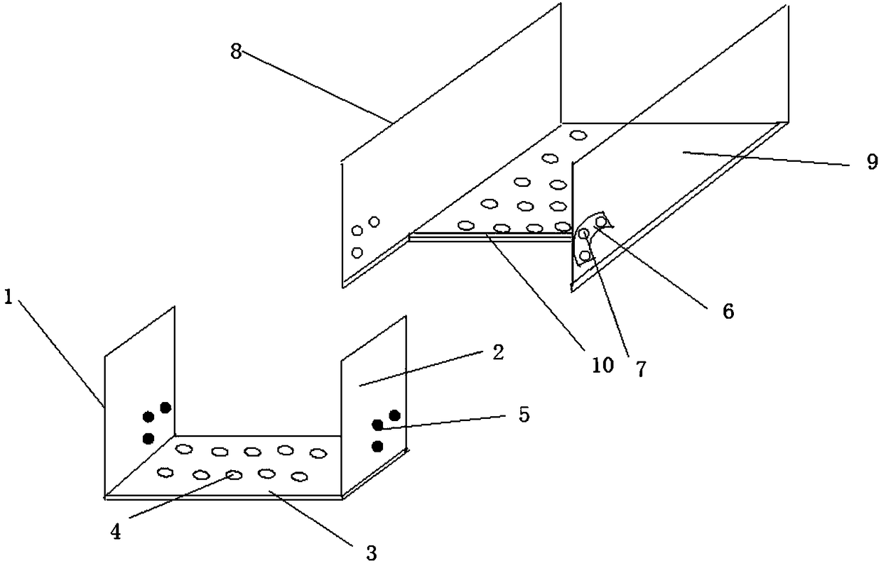
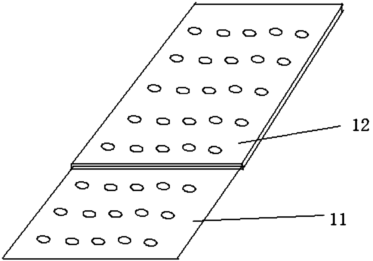
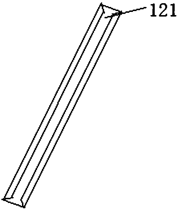
[0017] Such as Figure 1 to Figure 4 As shown, a rotatable tray-type cable bridge of the present invention includes a first bridge body and a second bridge body. The first bridge body includes the first left baffle 1 and the first right baffle 2, and the first left baffle 1 and the first right baffle 2 are all provided with connecting bolts 5, and the connecting bolts 5 include a connecting shell 51, a connecting rod 53 and the connecting spring 52 arranged between the connecting shell 51 and the connecting rod 53, the first bottom plate 3 is arranged between the first left fender 1 and the first right fender 2, and the first bottom plate 3 is a hollow structure. The second bridge body include...


PUM


Abstract

The invention discloses a rotatable tray type cable bridge. The rotatable tray type cable bridge comprises a first bridge body and a second bridge body; the first bridge frame body comprises a first left baffle and a first right baffle; connecting bolts are arranged on the first left baffle and the first right baffle; the second bridge body comprises a second left baffle and a second right baffle,and rotary clamping grooves are formed in the second left baffle and the second right baffle; bolt holes are formed in the rotary clamping grooves; a second bottom plate is arranged between the second left baffle and the second right baffle; the second bottom plate is of a telescopic structure; the second bottom plate comprises an outer bottom plate and an inner bottom plate, and a sliding clamping groove is formed in the inner side of the outer bottom plate; and the first bridge frame body and the second bridge frame body are connected with the bolt holes in a matched mode through connectingbolts. According to the rotatable tray type cable bridge, flexible connection of the bridge frame sections can be realized through rotation by virtue of setting of structures of the rotary clamping grooves, the connecting bolts and the bolt holes, and the corners can be flexibly connected.

Description

technical field [0001] The invention relates to a bridge, in particular to a rotatable tray type cable bridge. Background technique [0002] With the development of information technology and the improvement of living standards, the role of cables is becoming more and more prominent. Cable tray is a device used to fix cables, which can be divided into trough type bridge, tray type bridge, ladder type bridge, grid type bridge and other structures, among which tray type cable tray is the most widely used in petroleum, chemical industry, light industry, telecommunications, etc. kind of. Tray-type cable tray has the advantages of light weight, large load, beautiful appearance, simple structure, and easy heat dissipation. However, there are disadvantages such as integral molding, cumbersome transportation, and inflexible installation during use. Contents of the invention [0003] The technical problem to be solved by the present invention is to overcome the defects of the pr...

Claims


Application Information

Patent Timeline
IPC IPC(8): H02G3/04
CPCH02G3/0437H02G3/0406
Inventor 刘良宝
Owner 镇江宝源电仪设备有限公司
Why Eureka
Try Eureka