Pneumatic pin puller

A pin puller and airway technology, which is applied in the field of pneumatic pin pullers, can solve the problems of large operating space for hydraulic sources, affect normal use, and high labor intensity, and achieve the effects of easy portability, small use space, and convenient operation

Pending Publication Date: 2018-11-23
上海宝骜工业技术服务有限公司
View PDF0 Cites 2 Cited by
  • Summary
  • Abstract
  • Description
  • Claims
  • Application Information

AI Technical Summary

Problems solved by technology

[0003] One is to screw the corresponding bolts into the cylindrical pins, and pull out the positioning pins by knocking, prying, pulling, etc. This kind of disassembly makes the positioning of some precision-assembled parts no longer accurate after several disassembly and assembly, so that All kinds of problems have seriously affected its normal use, increased the workload of maintenance personnel, and caused certain safety hazards;
[0004] The second type uses the traditional manual pin puller (with hammer), relying on the force from the operator to quickly move the weight to the stop, and the kinetic energy is instantly converted into pin puller force to pull out the positioning pin. This method is labor-intensive , which is not conducive to safe production;
[0005] The third type uses a hydraulic pin puller, which can solve the above problems. There are certain advantages in removing the large positioning pin, but it requires a hydraulic source and a large operating space.

Method used


Image

  • Pneumatic pin puller
  • Pneumatic pin puller
  • Pneumatic pin puller

Examples


Embodiment Construction

[0019] In order to make the object, technical solution and advantages of the present invention clearer, the present invention will be further described in detail below in conjunction with the accompanying drawings and embodiments.

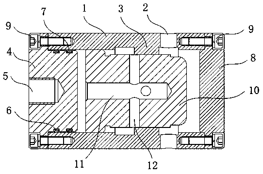
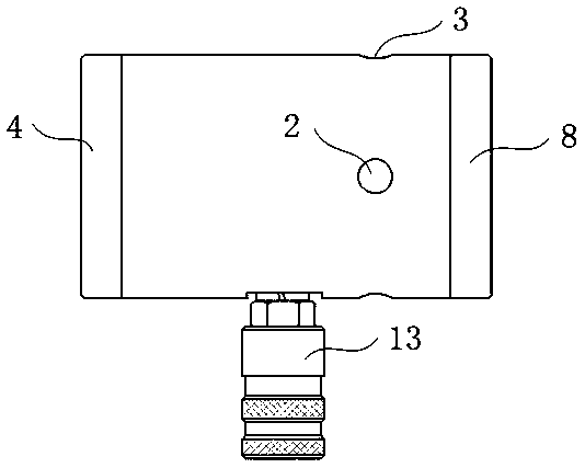
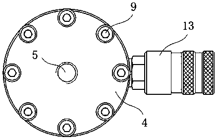
[0020] like Figure 1-3 As shown, the present invention discloses a pneumatic pin puller, which includes a cylinder body 1, a pulling disc 4, an impact disc 8 and a piston hammer 10. The cylinder body 1 is a cylindrical cylinder body, and the front and rear ends of the cylinder body 1 are respectively The drawing plate 4 and the impact plate 8 are installed and fixed by a number of hexagon socket head cap screws 9 at equal intervals in a ring, and the middle part of the cylinder body 1 is connected with a quick air exchange joint 13, and the cylinder body between the quick air exchange joint 13 and the impact plate 8 1 is provided with two sets of vent holes 2 perpendicular to each other, a set of limit protrusions 3 are provided on the inner wall ...


PUM


Abstract

The invention relates to the field of mechanical equipment and discloses a pneumatic pin puller. The pneumatic pin puller comprises a cylinder block, a piston hammer, a drawing plate and an impact plate. By structural optimization, a quick ventilation connector is connected with compressed air which serves as a power source; by matching of an air passage of the piston hammer and a release porous passage of the cylinder block, reciprocation of the piston hammer in the cylinder block is realized. By reasonable design, the pneumatic pin puller is simple in structure, detachable in mounting of each part and convenient to operate, once pin pulling operation can be completed only through control of compressed air inflow, and small operating and utilization space, portability and convenience in operation are realized.

Description

technical field [0001] The invention relates to the field of mechanical equipment, in particular to a pneumatic pin puller. Background technique [0002] Machining, assembly, and maintenance often use cylindrical pins for positioning, which is convenient for disassembly, assembly, and maintenance of equipment and tools, and achieves the purpose of rapid reset, adjustment, calibration, and maintenance of accuracy. There are several common methods for removing cylindrical pins with internal thread holes: [0003] One is to screw the corresponding bolts into the cylindrical pins, and pull out the positioning pins by knocking, prying, pulling, etc. This kind of disassembly makes the positioning of some precision-assembled parts no longer accurate after several disassembly and assembly, so that All kinds of problems have seriously affected its normal use, increased the workload of maintenance personnel, and caused certain safety hazards; [0004] The second type uses the tradit...

Claims


Application Information

Patent Timeline
Patent Type & Authority Applications(China)
IPC IPC(8): B23P19/027
CPCB23P19/027
Inventor 路立祥
Owner 上海宝骜工业技术服务有限公司
Why Eureka
Try Eureka