
Brake for roller washing machine and roller washing machine

A drum washing machine and brake technology, which is applied to other washing machines, applications, washing devices, etc., can solve the problems affecting the service life of the transmission effect of the planetary gear mechanism, the structure of the clutch mechanism is complex, and the load of the planetary gear mechanism is large, so as to achieve various washing methods Minimization, simple structure, and fewer parts

Active Publication Date: 2018-11-23
WUXI LITTLE SWAN ELECTRIC CO LTD
View PDF4 Cites 6 Cited by
  • Summary
  • Abstract
  • Description
  • Claims
  • Application Information

AI Technical Summary

Problems solved by technology

[0004] However, since the inner cylinder itself is larger than the pulsator, and the inner cylinder needs to carry clothes and water during washing, the load on the planetary gear mechanism is relatively large, which in turn affects the power transmission effect of the planetary gear mechanism and its own service life.
Moreover, the drum-type washing machine realizes the switching of the drive mode of the driving part through the clutch mechanism part, and the structure of the clutch mechanism part is complicated and difficult to control.

Method used


Image

  • Brake for roller washing machine and roller washing machine
  • Brake for roller washing machine and roller washing machine
  • Brake for roller washing machine and roller washing machine

Examples


Embodiment Construction

[0073] Embodiments of the present invention are described in detail below, examples of which are shown in the drawings, wherein the same or similar reference numerals designate the same or similar elements or elements having the same or similar functions throughout. The embodiments described below by referring to the figures are exemplary only for explaining the present invention and should not be construed as limiting the present invention.

[0074] In describing the present invention, it should be understood that the terms "center", "length", "width", "thickness", "upper", "lower", "front", "rear", "left", " Right", "Vertical", "Horizontal", "Top", "Bottom", "Inner", "Outer", "Clockwise", "Counterclockwise", "Axial", "Radial", "Circumferential" ” and other indicated orientations or positional relationships are based on the orientations or positional relationships shown in the accompanying drawings, which are only for the convenience of describing the present invention and si...


PUM


Abstract

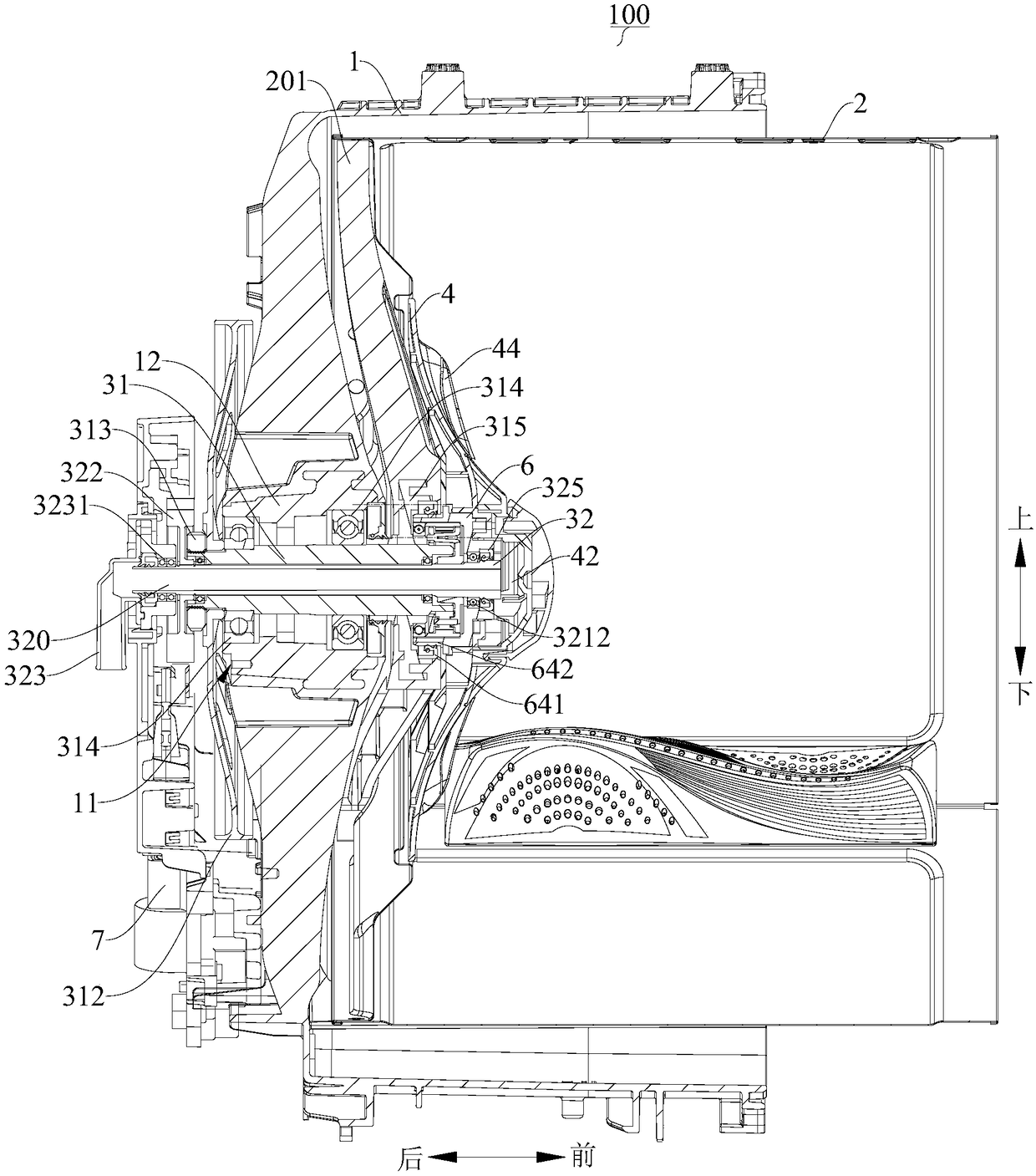
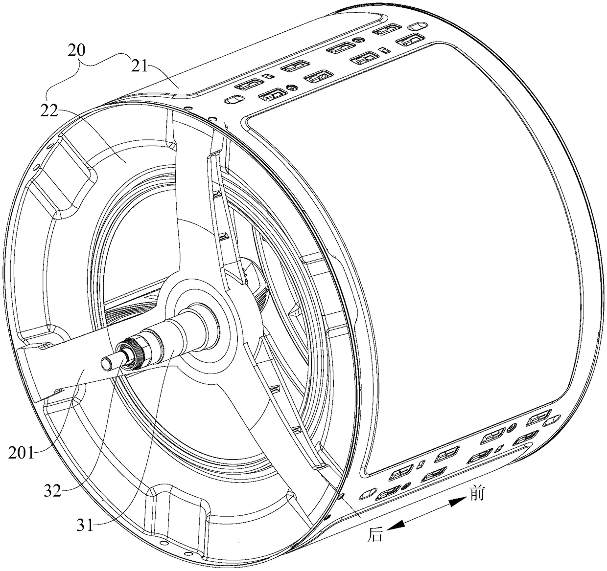
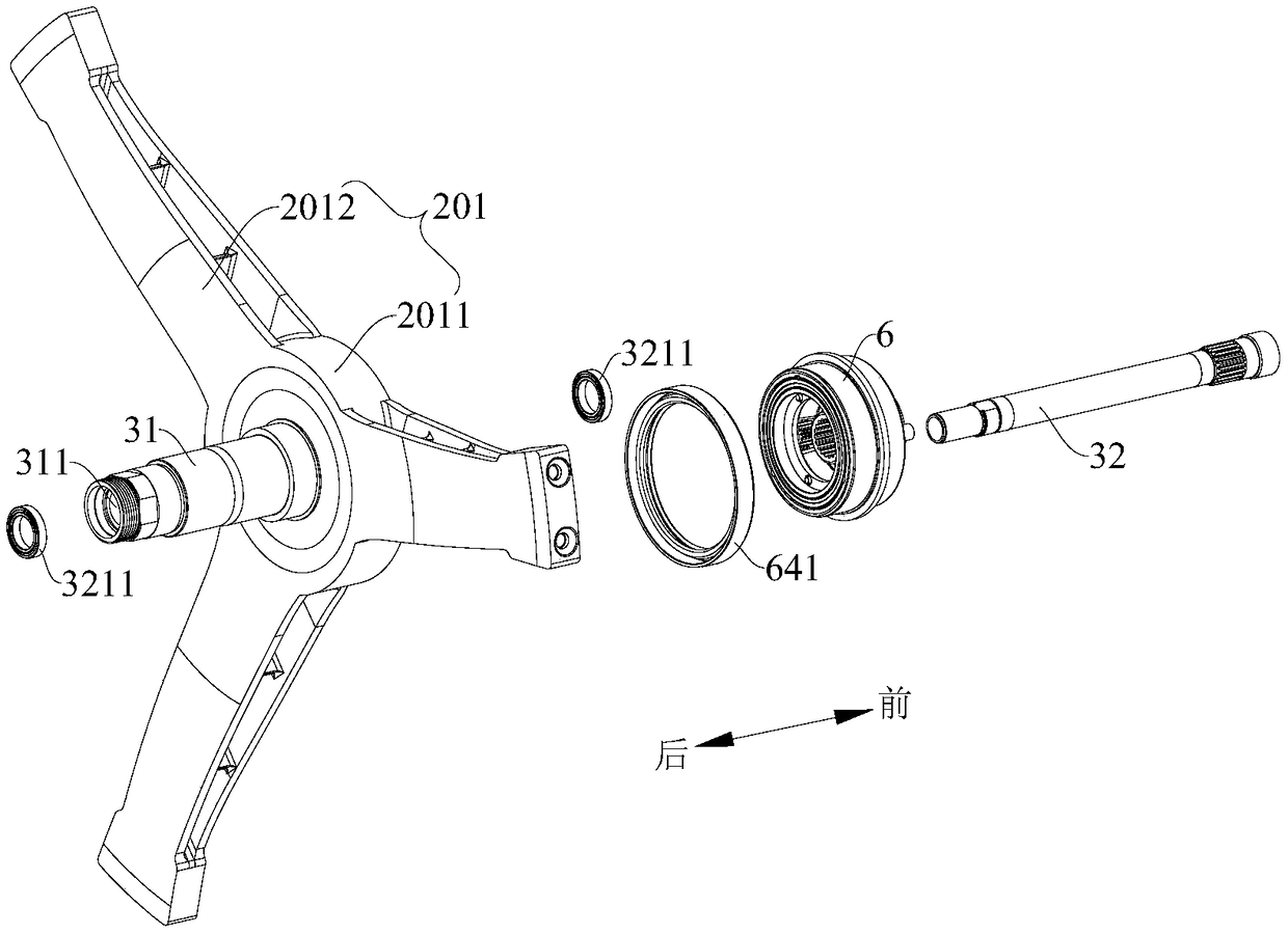
The invention discloses a brake for a roller washing machine and the roller washing machine. The brake comprises a brake disc, a brake base, a brake pawl, a brake rod and a brake driver, wherein the brake disc is arranged on a second shaft; the brake base is provided with a sliding rail; the brake pawl is arranged on the brake base in a switchable manner between the tightening state of tightly holding the brake disc and the unfolding state of releasing the brake disc; the brake rod is slidingly matched to the sliding rail between an extending position and a retraction position, the brake pawlis switched to the tightening state when the brake rod is located at the extending position, and the brake pawl is switched to the unfolding position when the brake rod is located at the retraction position; the brake driver is installed on the brake base and in transmission connection with the brake rod, and drives the brake rod to move between the extending position and the retraction position.By means of the brake for the roller washing machine in the embodiment, mode switching for cooperative work between a stirrer and an inner drum can be achieved, and the brake has the advantages of being simple in structure, convenient to control, stable and the like.

Description

technical field [0001] The present invention relates to the technical field of clothes processing devices, and more particularly, to a brake for a drum washing machine and the drum washing machine. Background technique [0002] When the drum washing machine is washing clothes, the inner cylinder rotates to drive the clothes and the water in the inner cylinder to rotate and wash the clothes. The baffles in the inner cylinder are used to lift and put down the clothes and beat the clothes through the inner peripheral surface of the inner cylinder. Yet, because its washing mode is single, has influenced washing effect. Therefore, a need for improvement exists. [0003] For this reason, a drum washing machine with a pulsator installed in the inner cylinder has been proposed in the related art. For example, PCT / CN2016 / 11037 discloses a drum type washing machine, which directly drives the pulsator to rotate through a motor, and at the same time, the motor drives the pulsator throu...

Claims


Application Information

Patent Timeline
Patent Type & Authority Applications(China)
IPC IPC(8): D06F37/30D06F37/40
CPCD06F37/30D06F37/40
Inventor 林光芳卢松刘祥宽顾超林
Owner WUXI LITTLE SWAN ELECTRIC CO LTD
Learn More