Scroll compressor

一种涡旋压缩机、压缩机构的技术,应用在涡旋压缩机领域,能够解决刀具切削断续、卷板间隙扩大、涡旋压缩机性能降低等问题

Active Publication Date: 2018-11-23
HITACHI JOHNSON CONTROLS AIR CONDITIONING INC
View PDF11 Cites 2 Cited by
  • Summary
  • Abstract
  • Description
  • Claims
  • Application Information

AI Technical Summary

Problems solved by technology

[0012] However, in the technology of Patent Document 1, the circumferential groove of the above-mentioned fixed scroll is disconnected from the crankcase tower of the above-mentioned crankcase at four places in the circumferential direction. In the case of processing the box, the cutting of the tool becomes intermittent
Therefore, whenever the tool comes into contact with the workpiece, a sudden load acts on the tool, and there is a problem that the tool is tilted and uncut is formed.
[0013] In particular, for the crank case, since the notch is formed between the above-mentioned crank case towers, the strength of the crank case tower is lowered, and chatter marks (micro-vibration) are likely to occur.
Therefore, there is also the problem that the processing accuracy of the inner peripheral surface of the above-mentioned crankcase tower is lowered.
[0014] If the processing accuracy is lowered, the gap between the arc surface of the groove and the inner peripheral surface of the crankcase tower, and the gap between the circumferential end of the groove and the circumferential end of the crankcase tower need to be set larger. , There is a problem that the displacement of the fixed scroll and the orbiting scroll occurs, or the gap between the wraps expands, and the excessive wrap contact, which leads to a decrease in the performance of the scroll compressor

Method used


Image

  • Scroll compressor
  • Scroll compressor
  • Scroll compressor

Examples


Embodiment 1

[0030] use Figure 1 to Figure 6 , Embodiment 1 of the scroll compressor of the present invention will be described.

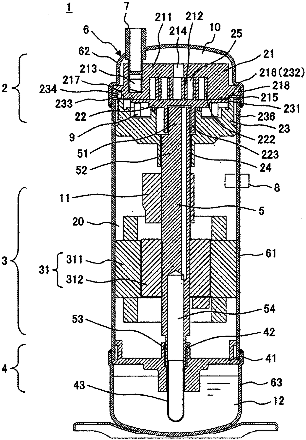
[0031] First, use figure 1 The overall configuration of the scroll compressor of the first embodiment will be described. figure 1 It is a longitudinal cross-sectional view showing the overall configuration of the scroll compressor of the first embodiment.

[0032] The scroll compressor 1 is configured to house a compression mechanism unit 2 , a drive unit 3 , an oil supply mechanism unit 4 , a rotating shaft 5 , and the like in a closed container 6 . In this example, from figure 1 From the upper part shown, the compression mechanism part 2, the drive part 3, and the oil supply mechanism part 4 are arranged in the above-mentioned closed container 6 in order, and the above-mentioned compression mechanism part 2, the above-mentioned drive part 3 and the above-mentioned oil supply mechanism part 4 The connection is made via the rotating shaft 5 .

[0033] The...


PUM


Abstract

A scroll compressor provided by the invention is capable of positioning and assembling a fixed scroll and an orbiting scroll with high precision with the elimination of a centering process or a fastening bolt during an assembling process. The scroll compressor includes a hermetically sealed container and a compression mechanism having a frame, a fixed scroll and an orbiting scroll. The fixed scroll includes a cylindrical portion formed in a circumferential direction on an outer circumferential side of a fixed wrap, a flange provided in the circumferential direction further outside of the cylindrical portion, and a first hole provided in the flange in an axial direction. The frame includes an inner circumferential surface into which the cylindrical portion of the fixed scroll is inserted and fitted, a flange which is provided in the circumferential direction further outside of the inner circumferential surface, and a second hole in the axial direction which is provided in a position ofthe flange opposite to the first hole. The scroll compressor further comprises: a knock pin that is inserted in the first hole and the second hole to prevent the frame and the fixed scroll from beingdisplaced in a rotational direction; and a fixing unit that fixes the frame and the fixed scroll to the hermetically sealed container.

Description

technical field [0001] The present invention relates to scroll compressors, and more particularly to the assembly of scroll compressors for air conditioners. Background technique [0002] In the assembly of a scroll compressor including a frame, a fixed scroll, and an orbiting scroll, as a method of centering the fixed scroll and the orbiting scroll, the following technique has been widely known in the past: making the rotation of the driving orbiting scroll The shaft rotates, and the fixed scroll is fastened to the frame with fastening bolts. [0003] In terms of this centering method, if the rotation direction of the fixed scroll and the frame is defined by positioning pins, etc., then there is an advantage that the center position relationship between the two can be automatically adjusted by the rotation of the rotation shaft. On the contrary, there is the following problem, that is, The assembly time of the compressor becomes longer, and fastening bolts for fixing the f...

Claims


Application Information

Patent Timeline
Patent Type & Authority Applications(China)
IPC IPC(8): F04C18/02F04C29/00
CPCF04C18/0223F04C29/00F04C2240/805F04C2240/30F04C18/0215F04C2230/603F04C23/008F04C2230/60F04C2230/231
Inventor 幸野雄森田惠理上桥佑介
Owner HITACHI JOHNSON CONTROLS AIR CONDITIONING INC
Why Eureka
Try Eureka