Supercharge Your Innovation With Domain-Expert AI Agents!

Timing chain tensioning device, engine and automobile

A technology of chain tensioning device and engine cylinder head, which is applied in the direction of engine components, machines/engines, transmissions, etc. It can solve the problems of unable to measure the amount of elongation of the timing chain wear, reduce maintenance costs, ensure phase accuracy, The effect of reducing detection time

Inactive Publication Date: 2018-11-23
CHONGQING CHANGAN AUTOMOBILE CO LTD
View PDF7 Cites 4 Cited by
  • Summary
  • Abstract
  • Description
  • Claims
  • Application Information

AI Technical Summary

Problems solved by technology

[0005] The purpose of the present invention is to provide a timing chain tensioner, engine and automobile, to solve the problem in the prior art that the wear and elongation of the timing chain cannot be measured without dismantling the timing chain

Method used


Image

  • Timing chain tensioning device, engine and automobile
  • Timing chain tensioning device, engine and automobile
  • Timing chain tensioning device, engine and automobile

Examples


Embodiment Construction

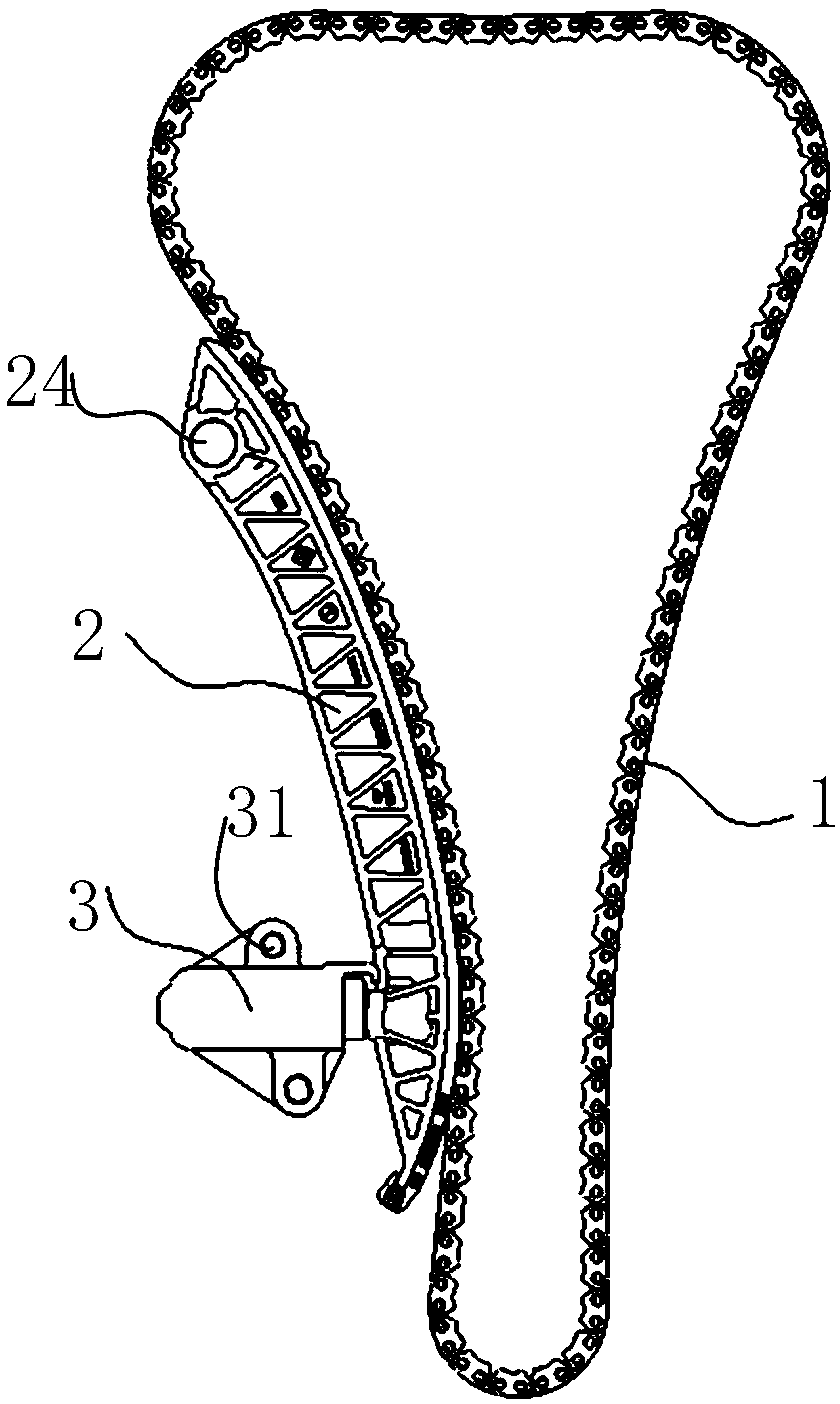
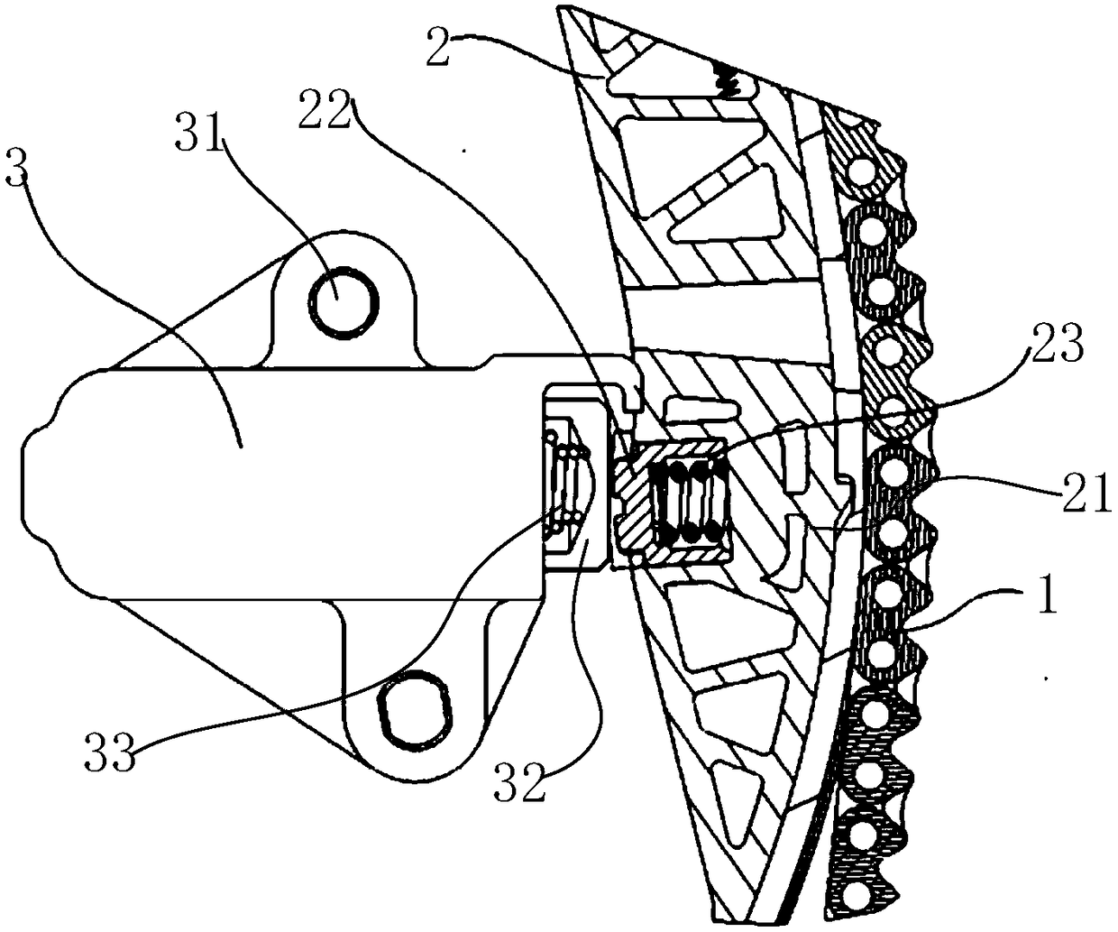
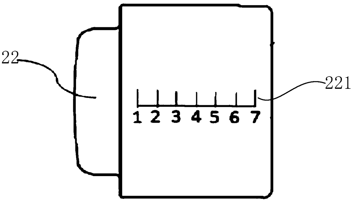
[0022] refer to Figure 1 to Figure 3 , the embodiment of the present invention provides a timing chain tensioning device, which includes a timing chain 1, a tensioning rail 2 and a tensioner 3 abutting against the tensioning rail 2. There is a guide rail 21, and the timing chain 1 is installed in the guide rail 21; the other end surface of the tension rail 2 facing the tensioner 3 is provided with a mounting groove, and a slidable sliding element 22 is embedded in the mounting groove, and the sliding element 22 Abutting against the tensioner 3, the end surface of the sliding element 22 opposite to the groove wall of the installation groove is provided with a scale line 221 for indicating the wear elongation of the timing chain 1; between the sliding element 22 and the groove bottom of the installation groove An elastic element 23 is provided. When the timing chain 1 is worn and elongated, the elastic element 23 pushes the sliding element 22 to slide away from the groove botto...


PUM


Abstract

The invention relates to a timing chain tensioning device, an engine and an automobile to solve the problem that in the prior art, the abrasion elongation of the timing chain cannot be measured on thepremise of not dismounting the timing chain. According to the technical scheme, the timing chain tensioning device comprises the timing chain, a tensioning rail and a tensioner abutting against the tensioning rail, one side end face of the tensioning rail is provided with a guide rail, and the timing chain is installed in the guide rail; the other side end face, facing the tensioner, of the tensioning rail is provided with an installation groove, a sliding element which can slide is embedded into the installation groove, the sliding element is connected with the tensioner in an abutting manner, the end face, opposite to the groove wall of the installation groove, of the sliding element is provided with scale marks used for indicating the abrasion elongation of the timing chain; and an elastic element is arranged between the sliding element and the groove bottom of the installation groove, when the timing chain is abraded to extend, the elastic element pushes the sliding element to slide in the direction far away from the groove bottom of the installation groove, and scale mark part on the sliding element is exposed out of the installation groove.

Description

technical field [0001] The invention relates to the technical field of automobile engines, in particular to a timing chain tensioner, an engine and an automobile. Background technique [0002] The gas distribution mechanism of an automobile engine is an important part of ensuring the normal operation of the engine. Two transmission modes are commonly used in the gas distribution mechanism, specifically: timing belt transmission and timing chain transmission. Because the advantage of the timing chain compared with the timing belt is that it has high structural strength and can carry higher power and torque, it is widely used. As we all know, the arrangement of the timing chain system is divided into tight side and loose side. Guide rails are arranged on the tight side and tension rails are used on the loose side to realize the guiding and tensioning of the timing chain. [0003] In an ideal state, the timing chain is maintenance-free for life. However, as the natural environ...

Claims


Application Information

Patent Timeline
Patent Type & Authority Applications(China)
IPC IPC(8): F16H7/08F02B77/08
CPCF02B77/081F16H7/08
Inventor 韦颂李春周敬乔
Owner CHONGQING CHANGAN AUTOMOBILE CO LTD
Features
  • R&D
  • Intellectual Property
  • Life Sciences
  • Materials
  • Tech Scout
  • Unparalleled Data Quality
  • Higher Quality Content
  • 60% Fewer Hallucinations
Learn More