A Roller of Planetary Roller Screw Pair for Improving Roller Force

A planetary roller and screw pair technology, applied in the direction of belts/chains/gears, mechanical equipment, transmission devices, etc., can solve the problems affecting the force of the rollers and transmission accuracy, waste of materials, difficulty in ensuring the consistency of the rollers, etc. question

Active Publication Date: 2021-01-15
XI AN JIAOTONG UNIV
View PDF1 Cites 0 Cited by
  • Summary
  • Abstract
  • Description
  • Claims
  • Application Information

AI Technical Summary

Problems solved by technology

The standard and reverse planetary roller screws are mainly composed of a screw, a nut and many rollers. The roller structure is divided into a middle thread section and two end gear sections: the middle thread section, the screw thread section and the thread of the nut. The gear segments at both ends are in contact with each other to transmit power and bear the load; the gear segments at both ends mesh with the inner ring gear of the standard planetary roller screw pair or the gear ring of the reverse planetary roller screw pair to reduce the sliding of each roller , to maintain the consistency of planetary motion, and in addition, it needs to be in contact with the lead screw; the gear segments at both ends of the roller mesh with the inner ring gear of the standard planetary roller screw pair or the gear ring of the reverse planetary roller screw pair The degree of overlap affects the stability of the transmission system; in addition, during the transmission process, the axial force generated by the roller due to the load has axial deformation and Hertzian contact deformation, which affects the force on the roller and the transmission accuracy.
[0003] There are gears and threads at both ends of the planetary roller screw roller. At present, the cutting process is used, which has low efficiency and serious material waste; in addition, the threads are generally cut first, and then the tooth profile is processed. Among the rod rollers, there are special requirements for the phase of the thread and the gear segment. The rollers of the same planetary roller screw pair must be exactly the same, and the phase consistency between the gear and the thread must be ensured during processing, but it is difficult to ensure the phase of the roller by cutting. Phase consistency between columns requires additional tooling to ensure phase accuracy and increase manufacturing cycle
[0004] In Chinese patent ZL201310034355.8, a new processing method for synchronous rolling forming of shaft parts with thread and gear characteristics is proposed. Using the corresponding mold, one-time rolling forming of shaft parts with thread and gear can improve manufacturing efficiency and ensure thread The phase accuracy with the gear, but the original planetary roller screw roller has a special complex structure of gears and threads at both ends of the roller, which is not conducive to synchronous rolling and forming rollers

Method used


Image

  • A Roller of Planetary Roller Screw Pair for Improving Roller Force
  • A Roller of Planetary Roller Screw Pair for Improving Roller Force
  • A Roller of Planetary Roller Screw Pair for Improving Roller Force

Examples


Embodiment 1

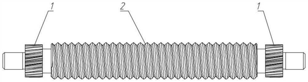
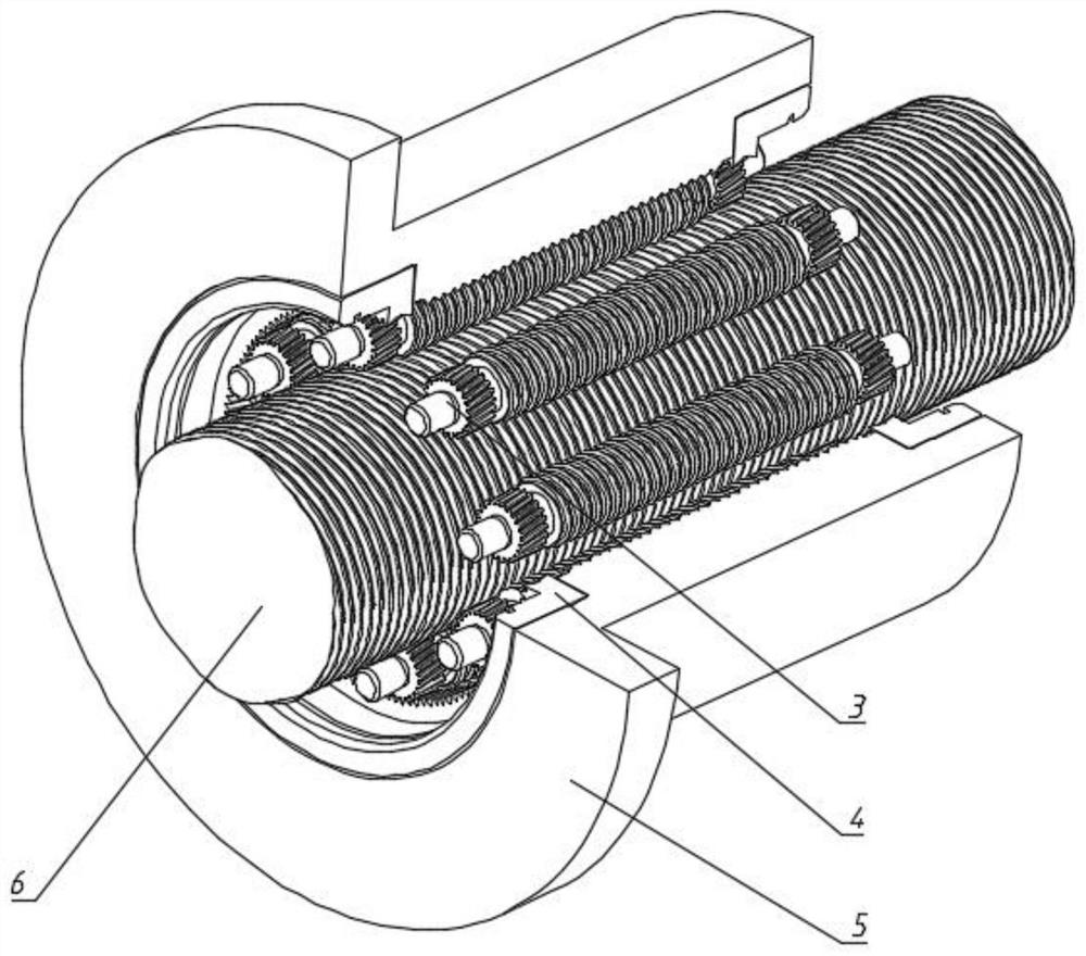
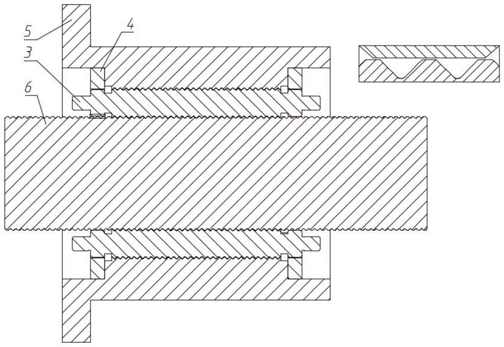
[0043] Embodiment 1, with reference to figure 1 , figure 2 and image 3 , the radius of the addendum circle of the gear segment structure 1 at both ends of the roller 3 is Its relationship with the first leading screw 6 is: Where a is the center distance between the roller 3 and the first lead screw 6, r a is the thread outer diameter parameter of the first lead screw 6;

[0044] Take the number of teeth of the gear segment structure 1 at both ends and the ring gear 4 as Z respectively 1 ,Z 2 , where Z 2 / Z 1 =i; take the end modulus of the gear segment structure 1 and the inner ring gear 4 at both ends as m t1 、m t2 ,Have Take the end face pressure angles of the gear segment structure 1 at both ends and the inner ring gear 4 as α t1 、α t2 , its value is selected according to the transmission requirements, and m t1 cosα t1 = m t2 cosα t2 ;;Take the helical gear helical angle of the two-end gear segment structure 1 and the inner ring gear 4 as β, which has t...

Embodiment 2

[0054] Embodiment 2, with reference to figure 1 and Figure 4 , in the reverse planetary roller screw, the radius of the addendum circle of the gear segment structure 1 at both ends of the roller 3 is Its relation with the second nut 9 is: Wherein a is the center distance between the roller 3 and the second lead screw 8, is the thread major diameter parameter of the second nut 9;

[0055] Take the number of teeth of gear segment structure 1 and gear 7 at both ends as Z 1 ,Z 3 , where Z 3 / Z 1 =i; take the end modulus of the gear segment structure 1 and the gear 7 at both ends as m t1 、m t3 ,Have Take the end face pressure angles of gear segment structure 1 and gear 7 at both ends as α t1 、α t3 , its value is selected according to the transmission requirements, and m t1 cosα t1 = m t3 cosα t3 ; Take the helix angle of the gear segment structure 1 at the two ends of the roller and the gear 7 as β, and its direction of rotation is opposite, and the direction of...


PUM


Abstract

A roller of a planetary roller screw pair for improving roller stress comprises gear section structures at the two ends and a middle thread section structure. The gear section structures at the two ends are helical tooth-shaped structures. For a standard planetary roller screw, the radius of addendum circles of the gear section structures at the two ends of the roller is reduced, the gear sectionstructures at the two ends are not in physical contact with a first lead screw, and the transmission ratio i of a roller gear to an inner gear ring accords with the kinematic relation of the roller, the first lead screw and a first nut of the planetary roller screw. In the same way, in a reverse planetary roller screw, the radius of addendum circles of the gear section structures at the two ends is reduced, the gear section structures at the two ends are not in physical contact with an internal thread of a second nut, and the transmission ratio i of a roller gear to a gear ring accords with the kinematic relation of the roller, a second lead screw and the second nut in the planetary roller screw. According to the roller, helical teeth at the two ends of the roller are only engaged with helical inner gear rings on the nuts or holder helical gears at the two ends of a short lead screw to do planetary motion, the axial force and axial deformation of the roller are reduced, the structure is simplified, and synchronous rolling forming is convenient.

Description

technical field [0001] The invention belongs to the technical field of mechanical transmission, and in particular relates to a roller of a planetary roller screw pair for improving the force on the roller. Background technique [0002] There are two types of traditional planetary roller screw structures: standard type and reverse type. The standard type planetary roller screw has a long screw and short nut structure, and there is no axial relative movement between the roller and the nut; reverse type The planetary roller screw has a short screw and long nut structure, and there is no axial relative movement between the roller and the screw. The standard and reverse planetary roller screws are mainly composed of a screw, a nut and many rollers. The roller structure is divided into a middle thread section and two end gear sections: the middle thread section, the screw thread section and the thread of the nut. The gear segments at both ends are in contact with each other to tr...

Claims


Application Information

Patent Timeline
Patent Type & Authority Patents(China)
IPC IPC(8): F16H25/22
CPCF16H25/2252
Inventor 张大伟卢昆银赵升吨
Owner XI AN JIAOTONG UNIV
Why Eureka
Try Eureka