Supercharge Your Innovation With Domain-Expert AI Agents!

Roller of planetary roller screw pair

A planetary roller and screw pair technology, applied in the direction of belts/chains/gears, mechanical equipment, transmission devices, etc., can solve the problems of unfavorable synchronous rolling forming rollers, waste of materials, low efficiency, etc.

Active Publication Date: 2020-01-21
XI AN JIAOTONG UNIV
View PDF8 Cites 0 Cited by
  • Summary
  • Abstract
  • Description
  • Claims
  • Application Information

AI Technical Summary

Problems solved by technology

[0003] There are gears and threads at both ends of the planetary roller screw roller. Currently, the cutting process is used, which has low efficiency and serious waste of materials; Among the rod rollers, there are special requirements for the phase of the thread and the gear segment. The rollers of the same planetary roller screw pair must be exactly the same, and the phase consistency between the gear and the thread must be ensured during processing, but it is difficult to ensure the phase of the roller by cutting. Phase consistency between columns requires additional tooling to ensure phase accuracy and increase manufacturing cycle
[0004] In Chinese patent ZL201310034355.8, a new processing method for synchronous rolling forming of shaft parts with thread and gear characteristics is proposed. Using the corresponding mold, one-time rolling forming of shaft parts with thread and gear can improve manufacturing efficiency and ensure thread The phase accuracy with the gear, but the original planetary roller screw roller has a special complex structure of gears and threads at both ends of the roller, which is not conducive to synchronous rolling and forming rollers

Method used


Image

  • Roller of planetary roller screw pair
  • Roller of planetary roller screw pair
  • Roller of planetary roller screw pair

Examples


Embodiment 1

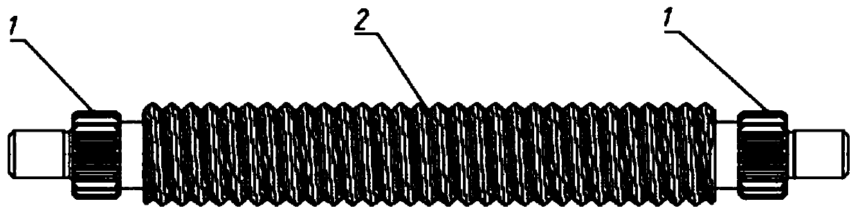
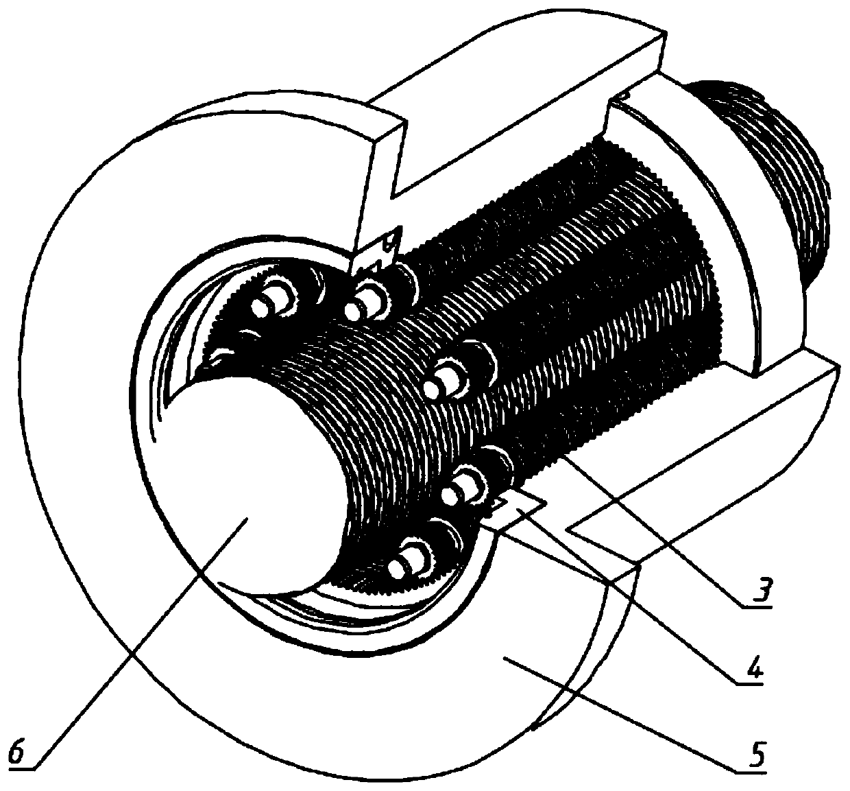
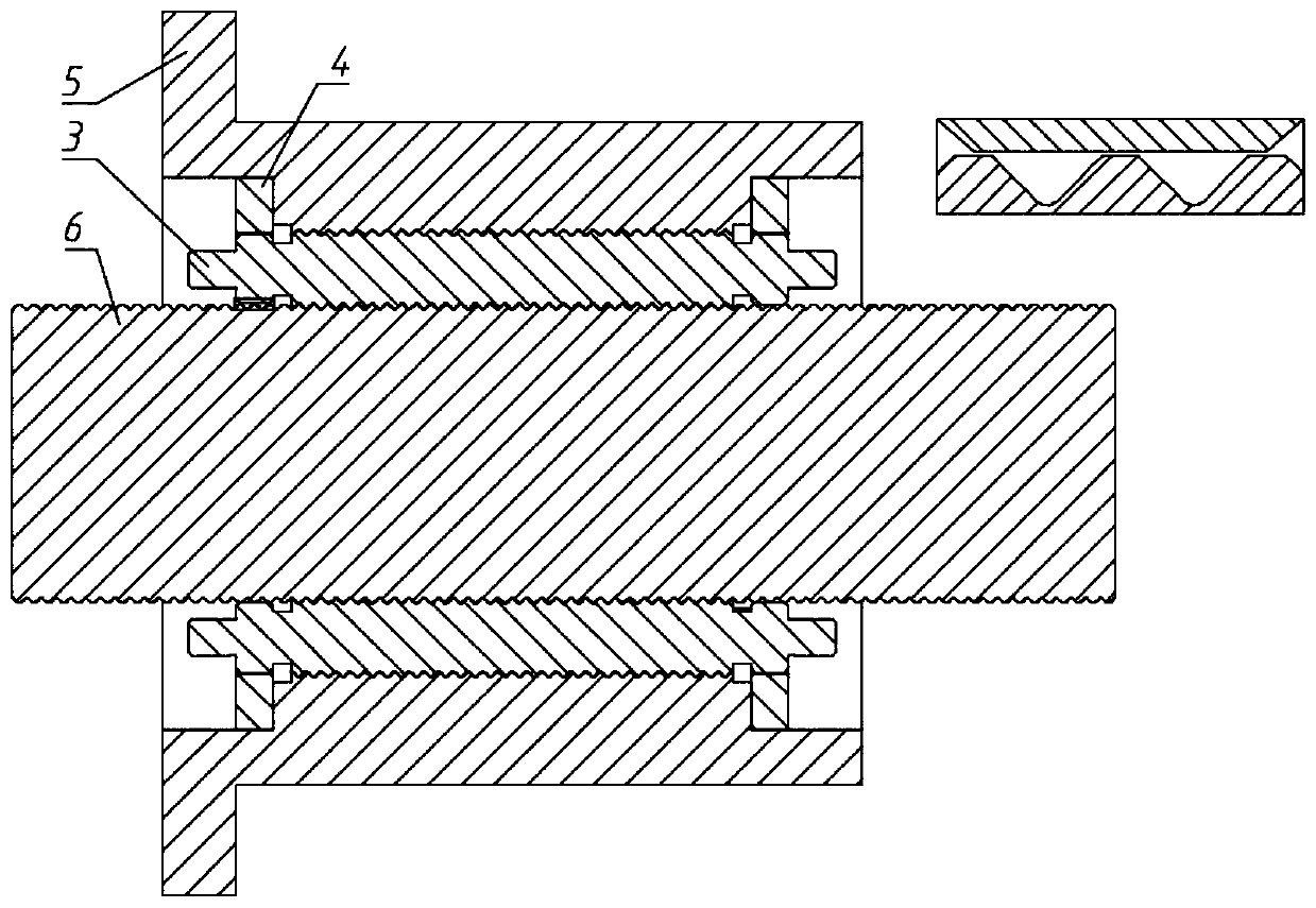
[0042] Embodiment 1, with reference to figure 1 , figure 2 and image 3 , for the standard planetary roller screw, the radius r of the addendum circle of the gear section structure at both ends of the roller a1 Reduced, no physical contact with the first lead screw, and the transmission ratio i of the roller gear and the ring gear conforms to the motion relationship of the roller, the first lead screw and the first nut in the planetary roller screw;

[0043] If it is a standard planetary roller screw pair, the implementation method of the gear segment structure of the rollers of the planetary roller screw pair is as follows:

[0044] The radius of the addendum circle of the gear segment structure 1 at both ends of the roller 3 is Its relationship with the first lead screw 6 is: Where a is the center distance between the roller 3 and the first lead screw 6, r a is the thread outer diameter parameter of the lead screw 6;

[0045] Take the number of teeth of the gear seg...

Embodiment 2

[0055] Embodiment 2, with reference to figure 1 and Figure 4 , in the reverse planetary roller screw, the radius r of the addendum circle of the gear section structure at both ends a1 Reduced, no physical contact with the internal thread of the second nut, the transmission ratio i of the roller gear and the gear ring conforms to the motion relationship of the roller in the planetary roller screw, the second screw and the second nut.

[0056] If it is a reverse planetary roller screw pair, the implementation method of the gear segment structure 1 at both ends of the planetary roller screw roller is as follows:

[0057] Take the radius of the addendum circle of the gear segment structure 1 at both ends of the roller 3 as Its relation with the second nut 9 is: Wherein a is the center distance between the roller 3 and the second lead screw 8, is the thread major diameter parameter of the second nut 9;

[0058] Take the number of teeth of gear segment structure 1 and gear ...


PUM


Abstract

The invention discloses a roller of a planetary roller screw pair. The roller comprises two end gear section structures and a middle threaded section structure, wherein the two end gear section structures are tooth-shaped structures; for a standard planetary roller screw, the addendum circle radius ra1 of the two end gear section structures of the roller is reduced, and the two end gear section structures are not in physical contact with a first screw; the transmission ratio i of a roller gear to an inner gear ring accords with the motion relation among the roller in the planetary roller screw, the first screw and a first nut; similarly, in a reverse planetary roller screw, the addendum circle radius ra1 of the two end gear section structures is reduced, and the two end gear section structures are not in physical contact with an internal thread of a second nut; and the transmission ratio i of the roller gear to a gear ring accords with the motion relation among the roller in the planetary roller screw, a second screw and the second nut. According to the roller, two end gears of the roller are only meshed with the inner gear ring on the nut or retainer gears at the two ends of a short screw to perform planetary motion, and meanwhile, the motion law in the planetary roller screw pair is kept unchanged, so that the structure is simplified, and synchronous rolling machining formingis facilitated.

Description

technical field [0001] The invention belongs to the technical field of mechanical transmission, and in particular relates to a roller of a planetary roller screw pair. Background technique [0002] There are two types of conventional planetary roller screw structures: standard and reverse. The standard planetary roller screw has a long screw and short nut structure, and there is no axial relative movement between the roller and the nut; the reverse planetary roller screw has a short screw and long nut structure, and the roller and the screw There is no axial relative movement between them. The standard and reverse planetary roller screws are mainly composed of a screw, a nut and many rollers. The roller structure is divided into a middle thread section and two end gear sections: the middle thread section, the screw thread section and the thread of the nut. The gear segments at both ends are in contact with each other to transmit power and bear the load; the gear segments a...

Claims


Application Information

Patent Timeline
IPC IPC(8): F16H25/22F16H25/24
CPCF16H25/2252F16H25/24
Inventor 张大伟卢昆银赵升吨
Owner XI AN JIAOTONG UNIV
Features
  • R&D
  • Intellectual Property
  • Life Sciences
  • Materials
  • Tech Scout
  • Unparalleled Data Quality
  • Higher Quality Content
  • 60% Fewer Hallucinations
Learn More