Electric water heater for instant electric water heater or electric fireplace
A technology for electric water heaters and electric water heaters, which is applied to circuit devices, water heaters, fluid heaters, etc., and can solve problems such as large diameters of power supply lines, affecting sales, and high power of electric heating tubes.
- Summary
- Abstract
- Description
- Claims
- Application Information
AI Technical Summary
Problems solved by technology
Method used
Image
Examples
Embodiment 1
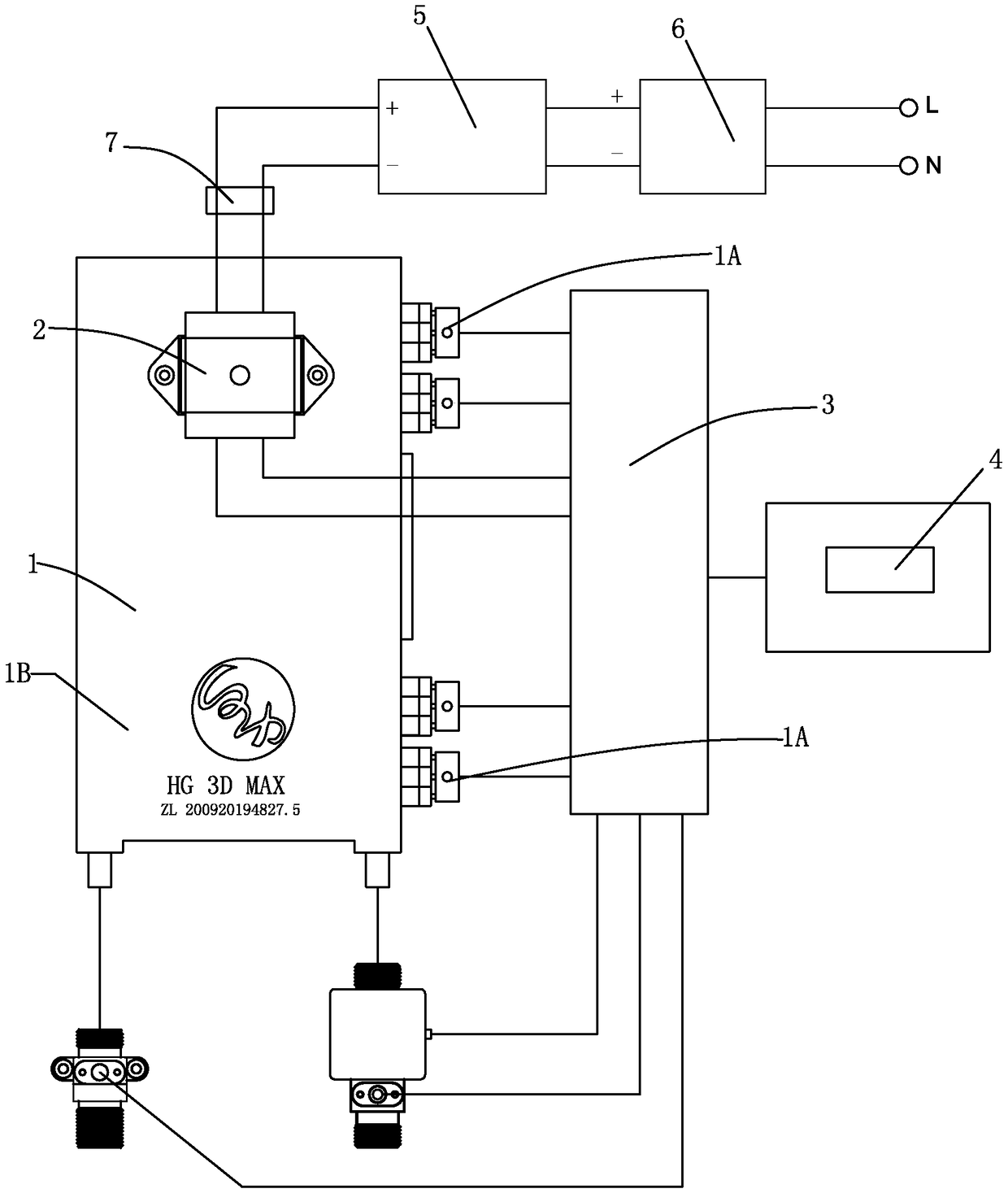
[0026] like figure 1 As shown, an electric water heater for an instant electric water heater or an electric fireplace includes an electric water heater body 1, a dry-burn protection thermostat 2, a control device 3 and an operation display panel 4. The electric water heater body 1 includes several The electric heating pipe 1A, the water pipe (not shown in the figure) and the metal shell 1B that wraps the electric heating pipe and the water pipe; the mains power supply, the anti-dry thermostat 2, the control device 3 and the electric heating pipe 1A are connected in sequence .
[0027] Also includes accumulator 5 and charger 6;
[0028] The mains power supply, charger 6, storage battery 5, anti-dry heating thermostat 2, and control device 3 are connected in sequence.
[0029] It also includes an anti-leakage detection transformer 7, and the anti-leakage detection transformer 7 is arranged on the line between the battery 5 and the anti-dry heating temperature controller 2.
Embodiment 2
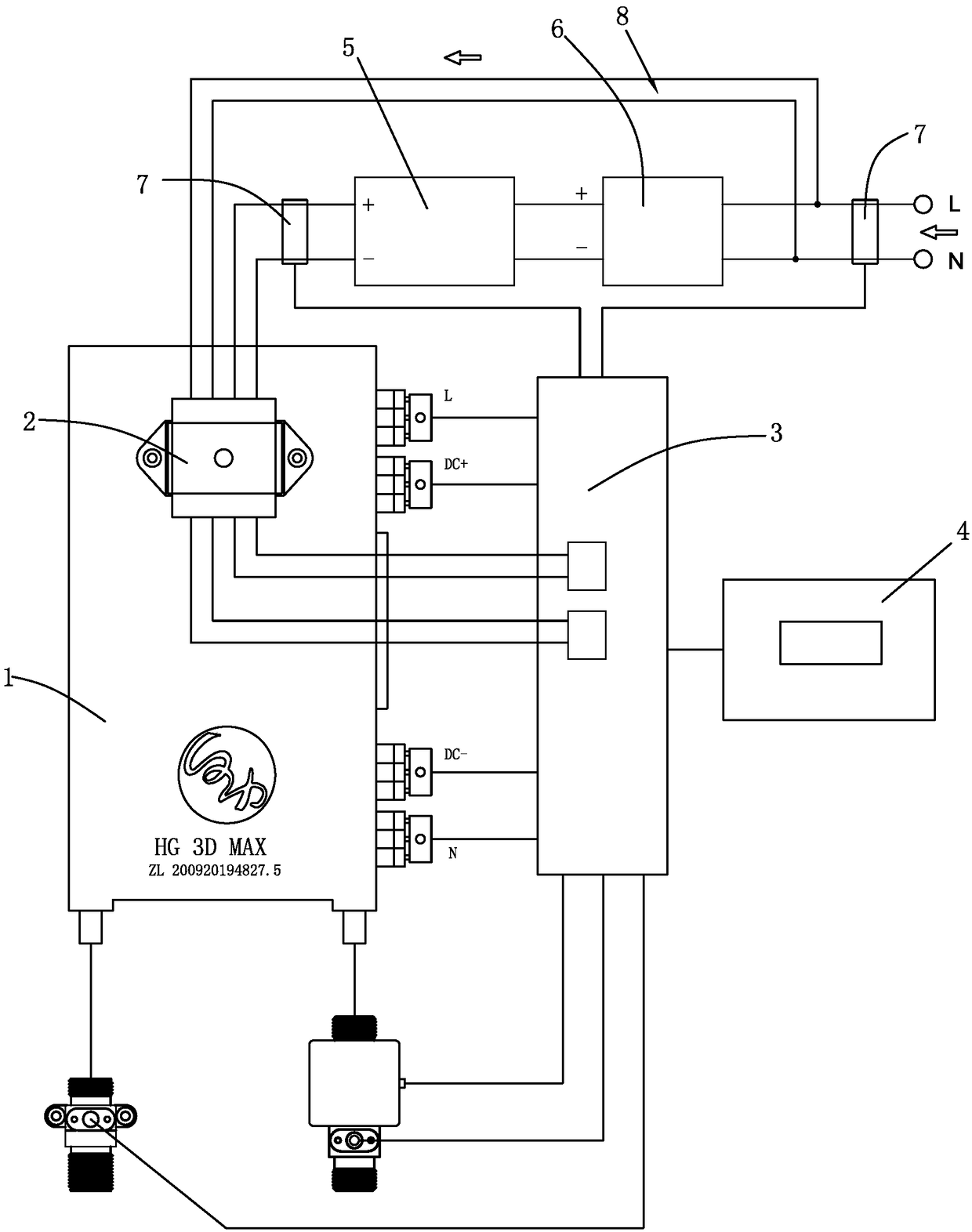
[0031] like figure 2 As shown, also includes an alternating current circuit 8;
[0032] One end of the AC line 8 is connected to the connection between the charger 6 and the commercial power supply, and the other end is connected to the anti-dry heating thermostat 2 .
[0033] Also includes leakage prevention detection transformer 7;
[0034] The anti-leakage detection transformer 7 is located at the output end of the storage battery 5;
[0035] Or the anti-leakage detection transformer 7 is arranged on the line between the AC line 8 and the mains power supply connection and the mains power supply;
[0036] Or one anti-leakage detection transformer 7 is arranged at the output end of the storage battery 5, and the other anti-leakage detection transformer 7 is arranged on the line between the AC line 8 and the connection between the mains power supply and the mains power supply.
Embodiment 3
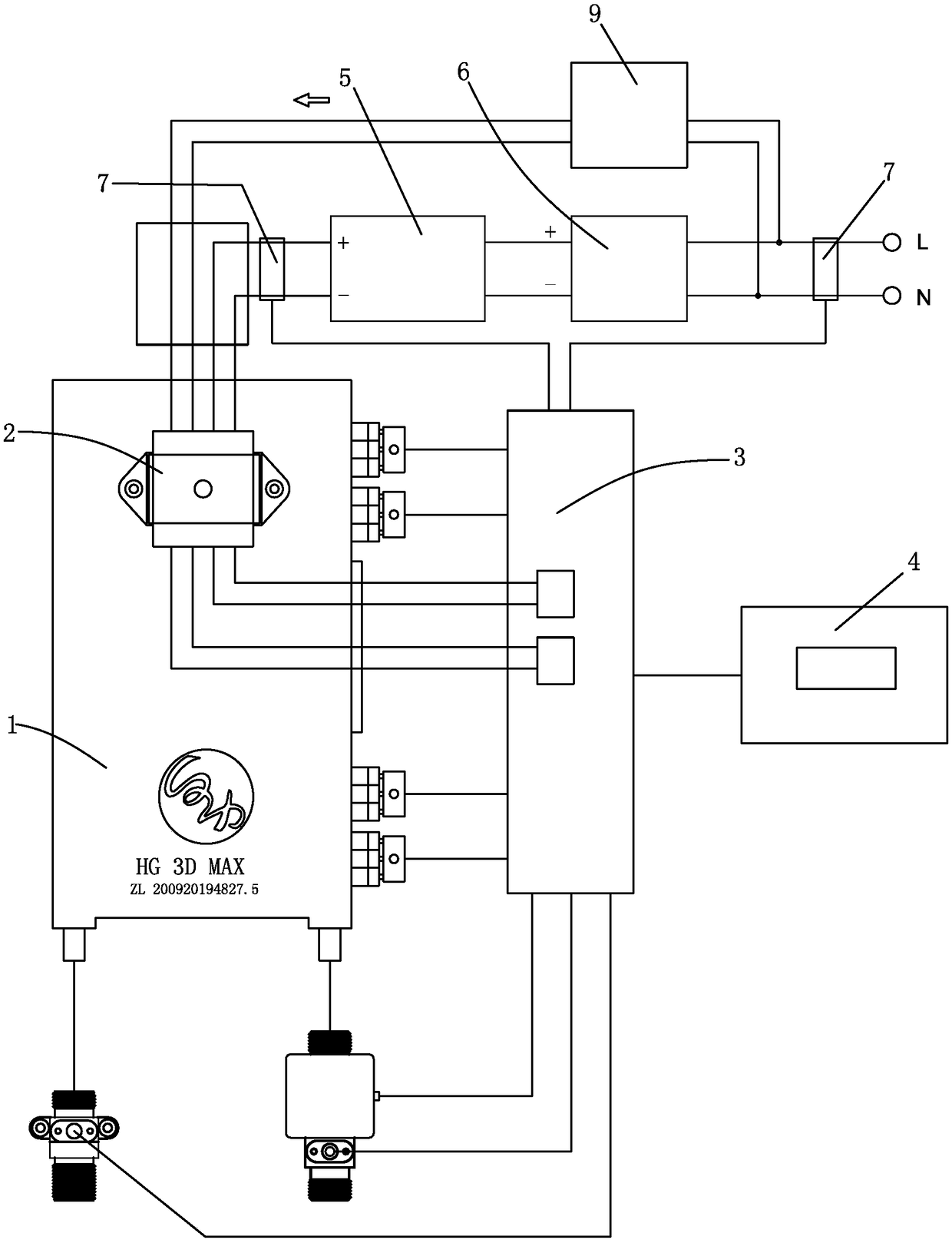
[0038] like image 3 As shown, also includes AC to DC converter 9;
[0039] One end of the AC-to-DC converter 9 is connected to the mains power supply, and the other end is connected to the anti-dry heating thermostat 2;
[0040] Or one end of the AC-to-DC converter 9 is connected to the commercial power supply, and the other end is connected in parallel with the output end of the storage battery 5 .
PUM
 Abstract
Description
Claims
Application Information
 - R&D
- Intellectual Property
- Life Sciences
- Materials
- Tech Scout
- Unparalleled Data Quality
- Higher Quality Content
- 60% Fewer Hallucinations
Browse by: Latest US Patents, China's latest patents, Technical Efficacy Thesaurus, Application Domain, Technology Topic, Popular Technical Reports.
© 2025 PatSnap. All rights reserved.Legal|Privacy policy|Modern Slavery Act Transparency Statement|Sitemap|About US| Contact US: help@patsnap.com


