Supercharge Your Innovation With Domain-Expert AI Agents!

Liquid crystal display panel and driving method thereof

A liquid crystal display panel and substrate technology, applied in static indicators, nonlinear optics, optics, etc., can solve problems such as overcompensation, signal output distortion, and small ripple voltage, so as to improve the display effect, avoid insufficient compensation, and avoid The effect of overcompensation

Inactive Publication Date: 2018-11-23
SHENZHEN CHINA STAR OPTOELECTRONICS TECH CO LTD
View PDF3 Cites 10 Cited by
  • Summary
  • Abstract
  • Description
  • Claims
  • Application Information

AI Technical Summary

Problems solved by technology

The disadvantage of this technology is that the ripple voltage detected by the CFcom signal is relatively small, and the waveform of the ripple voltage detected by the CFcom signal is shown in figure 2 As shown, the ripple voltage after PCB circuit board compensation is also small, which may not fully reflect the real situation of CFcom being coupled, while the ripple voltage detected by the Acom signal is relatively large, and the ripple voltage detected by the Acom signal Waveform diagram such as image 3 As shown, the ripple voltage after compensation by the PCB circuit board is also relatively large, which may cause overcompensation. The above two phenomena may lead to distortion of the Acom and CFcom signal output and affect the display effect of the LCD panel.

Method used


Image

  • Liquid crystal display panel and driving method thereof
  • Liquid crystal display panel and driving method thereof
  • Liquid crystal display panel and driving method thereof

Examples


Embodiment Construction

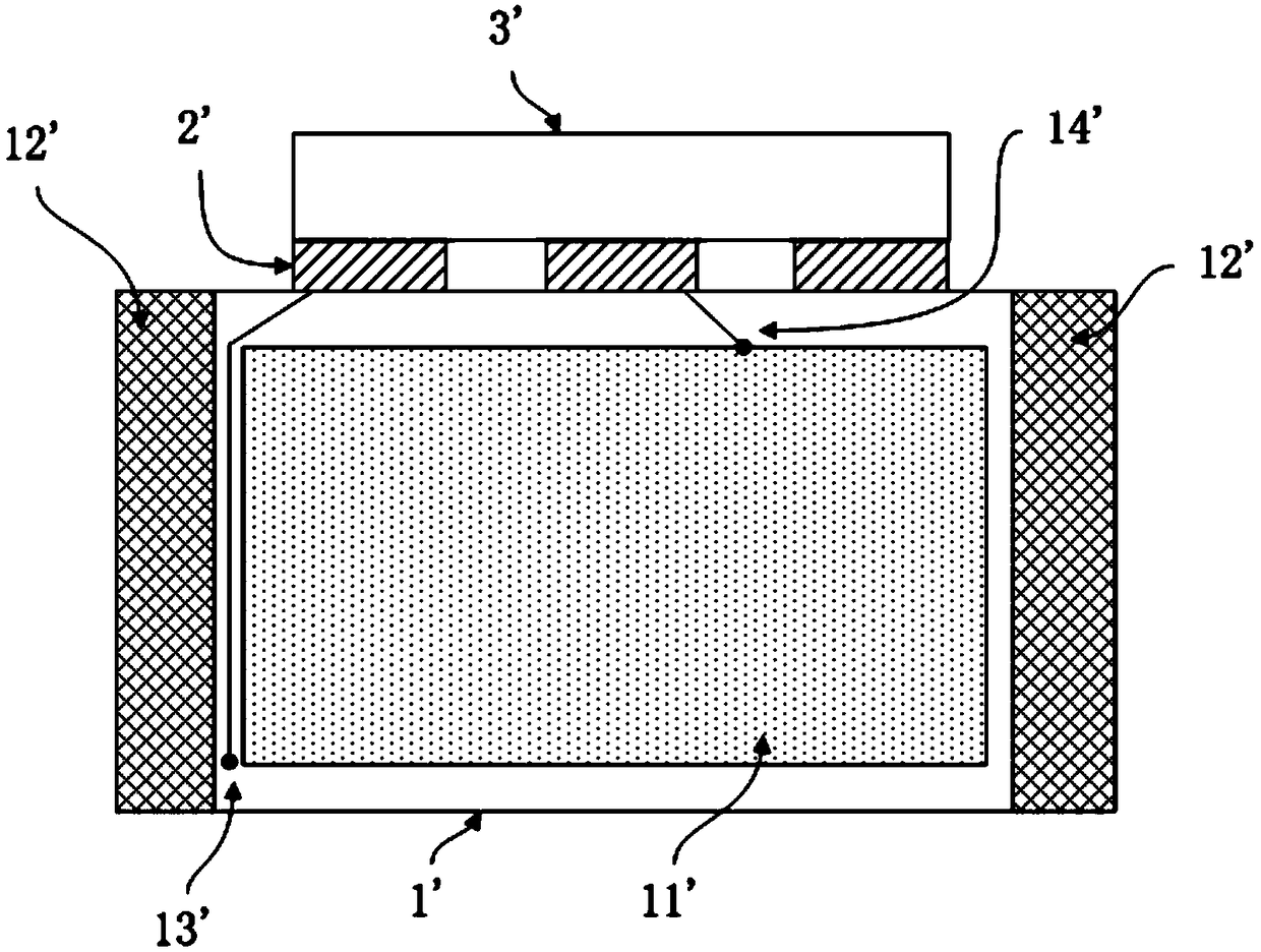
[0039] The invention provides a liquid crystal display panel, referring to Figure 4 and Figure 5 , which includes: a signal source circuit 41, an array substrate 1, a color filter substrate 2 disposed opposite to the array substrate 1, and a first compensation circuit 42 and / or a second compensation circuit 43; the array substrate 1 is provided with at least one first A common electrode line 13 and at least one second common electrode line 14 . Generally speaking, the liquid crystal display panel includes both the first compensation circuit 42 and the second compensation circuit 43 .

[0040] The signal source circuit 41 is used to output the first common voltage signal to the first common electrode line 13 and output the second common voltage signal to the second common electrode line 14; wherein, the first common electrode line 13 is used to provide The pixel circuit provides a first common voltage signal, and the second common electrode line 14 is electrically connected...


PUM


Abstract

The invention provides a liquid crystal display panel. A signal source circuit in the panel can output a first public voltage signal to a first public electrode wire and output a second public voltagesignal to a second public electrode wire; a first compensation circuit can obtain a first compensation voltage signal according to the first public voltage signal and a first feedback voltage signal,further can obtain a second compensation voltage signal according to the first public voltage signal and a second feedback voltage signal and further can transmit the compensation voltage signals tothe first public electrode wire; a second compensation circuit can obtain a third compensation voltage signal according to the second public voltage signal and a third feedback voltage signal, furthercan obtain a fourth compensation voltage signal according to the second public voltage signal and a fourth feedback voltage signal and further can transmit the compensation voltage signals to the second public electrode wire. The liquid crystal display panel disclosed by the invention can avoid insufficient compensation to the public voltage signals and can avoid overcompensation to the public voltage signals; furthermore, a display effect of the liquid crystal display panel is improved.

Description

technical field [0001] The invention relates to the field of display technology, in particular to a liquid crystal display panel and a driving method thereof. Background technique [0002] Liquid crystal display panel has become the mainstream display technology due to its advantages of high brightness, long life, wide viewing angle and large size display. Such as LCD TVs, mobile phones, digital cameras, notebook computer screens, car display screens, etc. [0003] The main structure of the liquid crystal display panel includes an array (Array) substrate, a color filter (Color Filter, CF) substrate and a liquid crystal layer between the array substrate and the color filter substrate, wherein the array substrate is the driving panel of the liquid crystal display panel, which includes TFT (Thin Film Transisto, thin film transistor) devices and various signals, etc. The main signals driven by the liquid crystal display panel include Acom (common voltage signal of the array su...

Claims


Application Information

Patent Timeline
IPC IPC(8): G02F1/133G02F1/1345G09G3/36
CPCG02F1/13306G02F1/13452G09G3/3696
Inventor 孙立志徐向阳
Owner SHENZHEN CHINA STAR OPTOELECTRONICS TECH CO LTD
Features
  • R&D
  • Intellectual Property
  • Life Sciences
  • Materials
  • Tech Scout
  • Unparalleled Data Quality
  • Higher Quality Content
  • 60% Fewer Hallucinations
Learn More