Power distribution cabinet convenient to install

A technology for power distribution cabinets and electrical components, which is applied in the field of power distribution cabinets that are easy to install, can solve problems such as road deformation and bulge, difficult electrical components, and inability to open power distribution cabinet doors, so as to increase ground clearance, Simple operation, compact utilization effect

Active Publication Date: 2018-11-23
吉林合纵信息技术有限公司
View PDF6 Cites 5 Cited by
  • Summary
  • Abstract
  • Description
  • Claims
  • Application Information

AI Technical Summary

Problems solved by technology

[0002] Power distribution cabinets are divided into power distribution cabinets, lighting distribution cabinets, and metering cabinets. They are the final equipment of the power distribution system. Most of the power distribution cabinets in the technology are equipped with a mounting plate, and through holes are drilled on the mounting plate. The mounting holes of the electrical components match the through holes of the mounting plate. The mounting holes of the components match, and it is easy to fail to install the electrical components. In addition, the doors of the power distribution cabinets in the prior art are generally opened outwards. Due to the cold winter, the land contains a certain amount of water. When the temperature drops below 0°C in winter, the land in a certain range under the surface will freeze. The frozen soil is called permafrost, which often occurs in permafrost areas. The phenomenon of ground uplift, that is, frost heave, will cause the road surface to deform and bulge, resulting in the inability to open the door of the power distribution cabinet

Method used


Image

  • Power distribution cabinet convenient to install
  • Power distribution cabinet convenient to install
  • Power distribution cabinet convenient to install

Examples


Embodiment 2

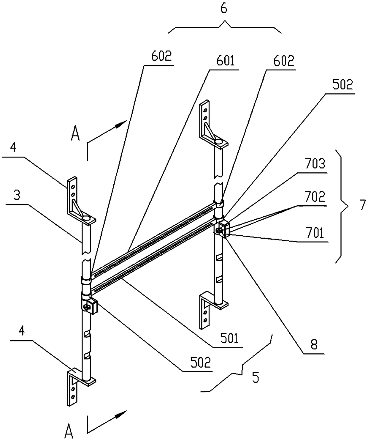
[0055] see Figure 7 shown;

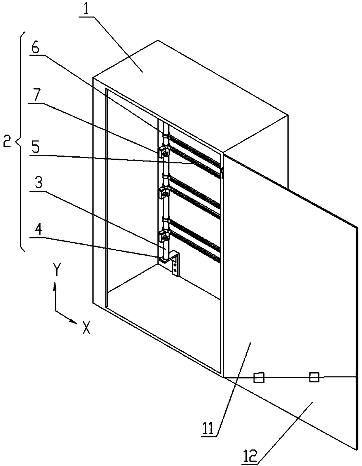
[0056] Preferably, the adjustable device 2 has a plurality of driven rods 6, and the driven rods 6 are fixedly connected to the power distribution cabinet body 1 through a linkage mechanism 9;

[0057] The upper and lower surfaces of the driven rod 6 parallel to the horizontal plane have T-shaped grooves, and a T-shaped slide block 603 capable of sliding along the T-shaped chute is housed in the T-shaped grooves;

[0058] Link mechanism 9 comprises mounting base 901 and connecting rod 903, and connecting rod 903 is rotatably connected with the connecting rod shaft of mounting base 901, and connecting rod rotating shaft is provided with external thread, and connecting rod 903 top is provided with compression handle 902, and handle 902 is connected with connecting rod. The rod shaft is threaded, and the handle 902 can control the rotation angle of the connecting rod 903. The two ends of the connecting rod 903 are connected to the T-shaped sliders 6...


PUM


Abstract

The invention discloses a power distribution cabinet convenient to install, and belongs to the technical field of electrical device. The invention comprises a power distribution cabinet body and a power distribution cabinet door, wherein an adjustable device is arranged in the power distribution cabinet body; the adjustable device has at least two columns of cylindrical structure; the columns areconnected with main adjusting rods and driven rods; the main adjusting rods are clamped with any one of notches arranged on the columns through positioning components; the driven rods are in sliding connection with the columns above or below the main adjusting rods; the power distribution cabinet body is rotationally coupled to the power distribution cabinet door through a hinge; the power distribution cabinet door has two door plates, and a second door plate can be folded with a first door plate at an included angle with the X axis when the first door plate is rotationally opened around the hinge. According to the power distribution cabinet convenient to install, a power distribution cabinet that is convenient for installing electrical components and is capable of opening the power distribution cabinet door when the ground is not flat is realized.

Description

technical field [0001] The invention relates to the technical field of electric equipment, in particular to an easy-to-install power distribution cabinet. Background technique [0002] Power distribution cabinets are divided into power distribution cabinets, lighting distribution cabinets, and metering cabinets. They are the final equipment of the power distribution system. Most of the power distribution cabinets in the technology are equipped with a mounting plate, and through holes are drilled on the mounting plate. The mounting holes of the electrical components match the through holes of the mounting plate. The mounting holes of the components match, and it is easy to fail to install the electrical components. In addition, the doors of the power distribution cabinets in the prior art are generally opened outwards. Due to the cold winter, the land contains a certain amount of water. When the temperature drops below 0°C in winter, the land in a certain range under the sur...

Claims


Application Information

Patent Timeline
Patent Type & Authority Applications(China)
IPC IPC(8): H02B1/38H02B1/30
CPCH02B1/30H02B1/38
Inventor 董鸿鹏李兴慧
Owner 吉林合纵信息技术有限公司
Why Eureka
Try Eureka