Camera plastic part

A camera and plastic technology, applied in the field of cameras, can solve the problems of easy locking failure, easy generation of debris in the plastic casing, etc., and achieve the effect of eliminating plastic debris, not easy to loosen and position deviation, and easy to disassemble and assemble repeatedly.

Inactive Publication Date: 2018-11-23
TRULY OPTO ELECTRONICS
View PDF6 Cites 2 Cited by
  • Summary
  • Abstract
  • Description
  • Claims
  • Application Information

AI Technical Summary

Problems solved by technology

[0005] The purpose of the present invention is to provide a camera plastic part, which effectively solves the problems that the PCB board is locked to the plastic shell by self-tapping screws, which is prone to debris and easy to lock failure.

Method used


Image

  • Camera plastic part
  • Camera plastic part

Examples


Embodiment Construction

[0020] The core of the present invention is to provide a camera plastic part, which effectively solves the problems that the PCB board is locked to the plastic shell by self-tapping screws, which is prone to debris and easy to lock failure.

[0021] The following will clearly and completely describe the technical solutions in the embodiments of the present invention with reference to the accompanying drawings in the embodiments of the present invention. Obviously, the described embodiments are only some, not all, embodiments of the present invention. Based on the embodiments of the present invention, all other embodiments obtained by persons of ordinary skill in the art without making creative efforts belong to the protection scope of the present invention.

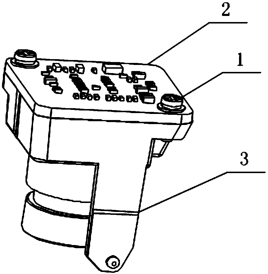
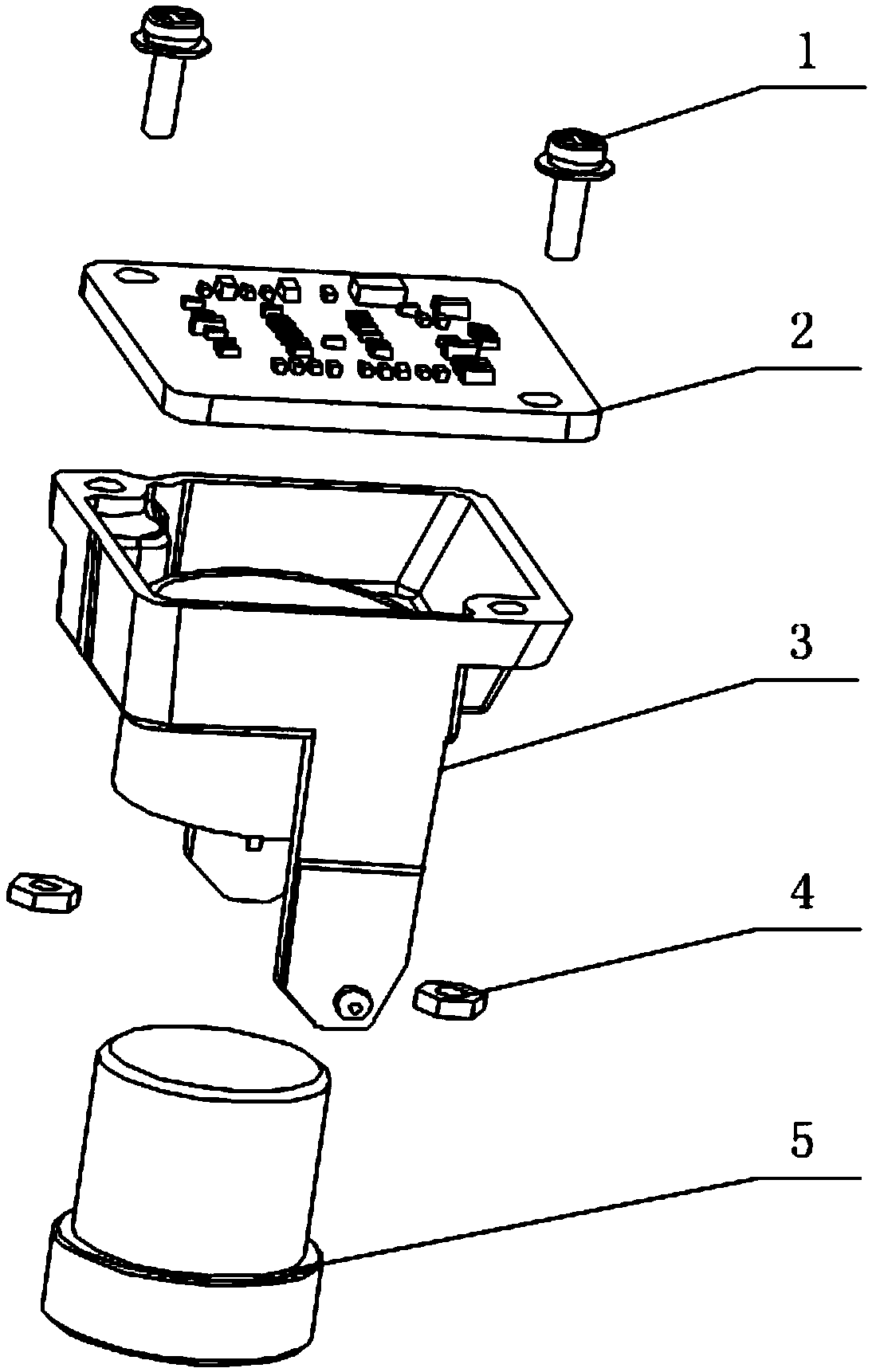
[0022] Please refer to figure 1 and figure 2 , figure 1 It is a schematic structural diagram of the plastic parts of the camera provided in a specific embodiment of the present invention; figure 2 for figure 1 explo...


PUM


Abstract

The invention discloses a camera plastic part. The camera plastic part comprises a plastic shell (3) for installing a lens (5), and a PCB board (2) packaged at the opening of the plastic shell (3); through holes are formed on the corresponding locations of the plastic shell (3) and the PCB board (2); the camera plastic part further comprises a combined bolt (1), the length of the combined bolt isgreater than the connecting face thickness of the plastic shell (3), and the combined bolt (1) orderly penetrates the through holes of the PCB board (2) and the plastic shell (3) and is fastened at the bottom surface of the plastic shell (3); the nut (4) is externally arranged at the external of the plastic shell (3) and is separated from the plastic shell (3). The camera plastic part effectivelysolves the problems that the chippings are easy to produce and the locking ineffectiveness is easy to produce since the PCB board is locked to the plastic shell through a self-tapping screw.

Description

technical field [0001] The invention relates to the technical field of cameras, in particular to a plastic part of a camera. Background technique [0002] The conventional camera plastic structure uses self-tapping screws as fasteners, and uses self-tapping screws to lock the PCB board to the plastic casing. [0003] However, in the process of using self-tapping screws to lock the PCB board to the plastic shell, plastic debris and dust will be generated; during the assembly process, it is necessary to disassemble and assemble the self-tapping screws several times to adjust the installation position of the PCB. The shell screw hole slips and the lock fails. [0004] To sum up, how to effectively solve the problems of using self-tapping screws to lock the PCB board to the plastic shell is easy to generate debris and easy to lock failure, which is an urgent problem for those skilled in the art. Contents of the invention [0005] The purpose of the present invention is to pr...

Claims


Application Information

Patent Timeline
Patent Type & Authority Applications(China)
IPC IPC(8): H04N5/225
CPCH04N23/51H04N23/50
Inventor 高超
Owner TRULY OPTO ELECTRONICS
Why Eureka
Try Eureka