Connecting device between drawer and slide rail

A technology of a coupling device and a drawer, which is applied in the directions of drawers, furniture parts, household appliances, etc., can solve the problems of inconsistent unlocking operation directions and separation directions, inconvenient disassembly operations, low assembly efficiency, etc., and achieves convenient and fast unlocking and disassembling operations. , reliable performance

Pending Publication Date: 2018-11-27
GUANGDONG TAIMING METAL PROD
View PDF1 Cites 0 Cited by
  • Summary
  • Abstract
  • Description
  • Claims
  • Application Information

AI Technical Summary

Problems solved by technology

[0002] In order to facilitate the connection and disassembly between the drawer and the slide rail, a corresponding device is often provided between the drawer and the slide rail. The development and application of this device are relatively mature, but the following problems still exist: 1. Due to the parts involved Many, resulting in low assembly efficiency and high cost; 2. Traditional devices are generally large in size due to structural limitations, occupying a considerable amount of space, and are not suitable for places with small spaces; 3. The unlocking operation direction of the device is often the same as The separation direction of the drawers is inconsistent, which requires the user to take into account multiple directions when disassembling the drawer, resulting in inconvenient disassembly operations

Method used


Image

  • Connecting device between drawer and slide rail
  • Connecting device between drawer and slide rail
  • Connecting device between drawer and slide rail

Examples


Embodiment Construction

[0039] The present invention will be further described below with reference to the drawings and embodiments.

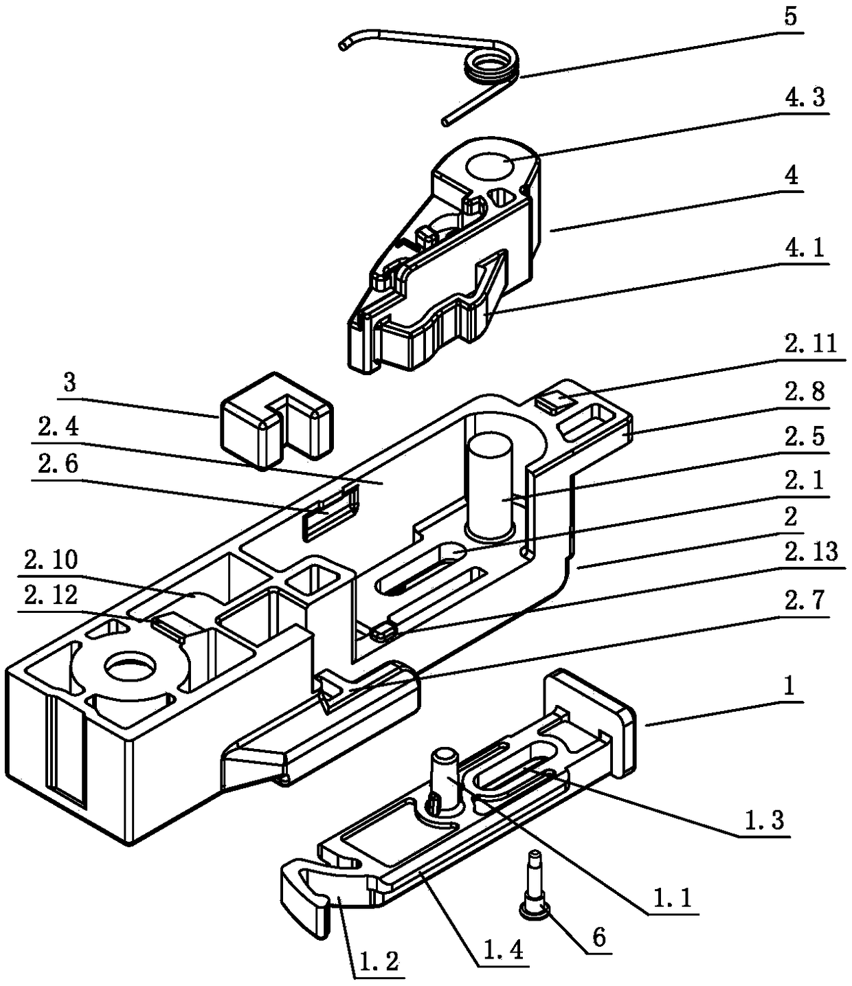
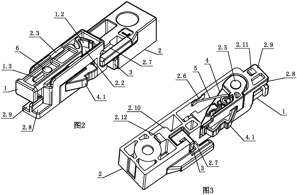
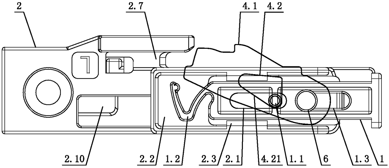
[0040] See Figure 1-Figure 31 , The connecting device between the drawer and the slide rail includes a connecting seat 2 fixed at the bottom of the drawer A, and a locking member 4 arranged on the connecting seat 2. The side of the locking member 4 is provided with a lock that is telescopic and movable relative to the connecting seat 2 Tongue 4.1; one end of the lock member 4 is hinged on the coupling base 2, and the first elastic member 5 is elastically reset and swings around the hinge. In the reset state, the lock tongue 4.1 is at least partially elastically extended out of the coupling base 2 with the lock member 4; The lock member 4 is provided with an unlocking groove 4.2 with an unlocking guide surface 4.21, the unlocking guide surface 4.21 is a flat surface (or arc surface); the coupling device C also includes an unlocking component 1 sliding on the coupling sea...


PUM


Abstract

The invention relates to a connecting device between a drawer and a slide rail, comprising a connecting seat fixed on the drawer and a locking part arranged on the connecting seat, wherein the lockingpart is provided with a locking tongue which is telescopically movable relative to the connecting seat. One end of the locking part is hinged on the coupling seat, and the locking tongue at least partially extends out of the coupling seat with the locking part elastically in the reset state through the elastic reset swinging of the first elastic part around the hinge. The locking part is providedwith an unlocking groove with an unlocking guide surface. The coupling device further comprises an unlocking part sliding on the coupling seat, wherein the unlocking part is provided with an unlocking shaft, the unlocking shaft slides with the unlocking part, and the unlocking guide surface is inclined with respect to the sliding direction of the unlocking shaft; When unlocking, the unlocking member is pushed in the direction of removal and separation of the drawer, and the unlocking shaft is squeezed and slid on the unlocking guide surface to drive the locking tabs to retreat into the coupling seat by mutual interaction. The connecting device has the characteristics of simple and reasonable structure, small and exquisite volume, convenient disassembly and assembly operation, reliable performance and long service life.

Description

Technical field [0001] The invention relates to a device for connecting a drawer and a sliding rail, in particular to a connecting device between a drawer and a sliding rail. Background technique [0002] In order to facilitate the connection and disassembly between the drawer and the slide rail, corresponding devices are often arranged between the drawer and the slide rail. The development and application of this device have been relatively mature, but the following problems still exist: 1. Due to the parts involved More, resulting in low assembly efficiency and high cost; 2. The traditional device is limited by the structure, and the volume is generally large, occupying a considerable space, and it is not suitable for places with small spaces; 3. The unlocking operation direction of the device is often the same The separation directions of the drawers are inconsistent, which requires the user to take into account operations in multiple directions when disassembling the drawer, ...

Claims


Application Information

Patent Timeline
Patent Type & Authority Applications(China)
IPC IPC(8): A47B88/407
CPCA47B88/407
Inventor 吴泰维
Owner GUANGDONG TAIMING METAL PROD
Why Eureka
Try Eureka