
Anti-shock packaging box

A packaging box and support plate technology, applied in the field of packaging supplies, can solve the problems of poor display, broken or damaged, and not environmentally friendly, and achieve the effects of good display performance and good shock resistance.

Active Publication Date: 2018-11-27
成都玩创科技有限公司
View PDF7 Cites 0 Cited by
  • Summary
  • Abstract
  • Description
  • Claims
  • Application Information

AI Technical Summary

Problems solved by technology

[0002] Nowadays, for the transportation of round fragile items (such as eggs, liquids in glass bottles, etc.) or round items that are not easy to be squeezed (such as oranges and other fruits), foam boxes and plastic products are often used as fillers for packaging, or round plastic boxes are used. and foam pallet packaging, the former takes up space and is not environmentally friendly, while the latter has a complicated preparation process and poor shock resistance, which is prone to breakage or damage during transportation; in addition, the products of the above two transportation methods are packaged In the box, the appearance of the product in the box cannot be observed from the outside, and the display is poor

Method used


Image

  • Anti-shock packaging box
  • Anti-shock packaging box
  • Anti-shock packaging box

Examples


Embodiment 1

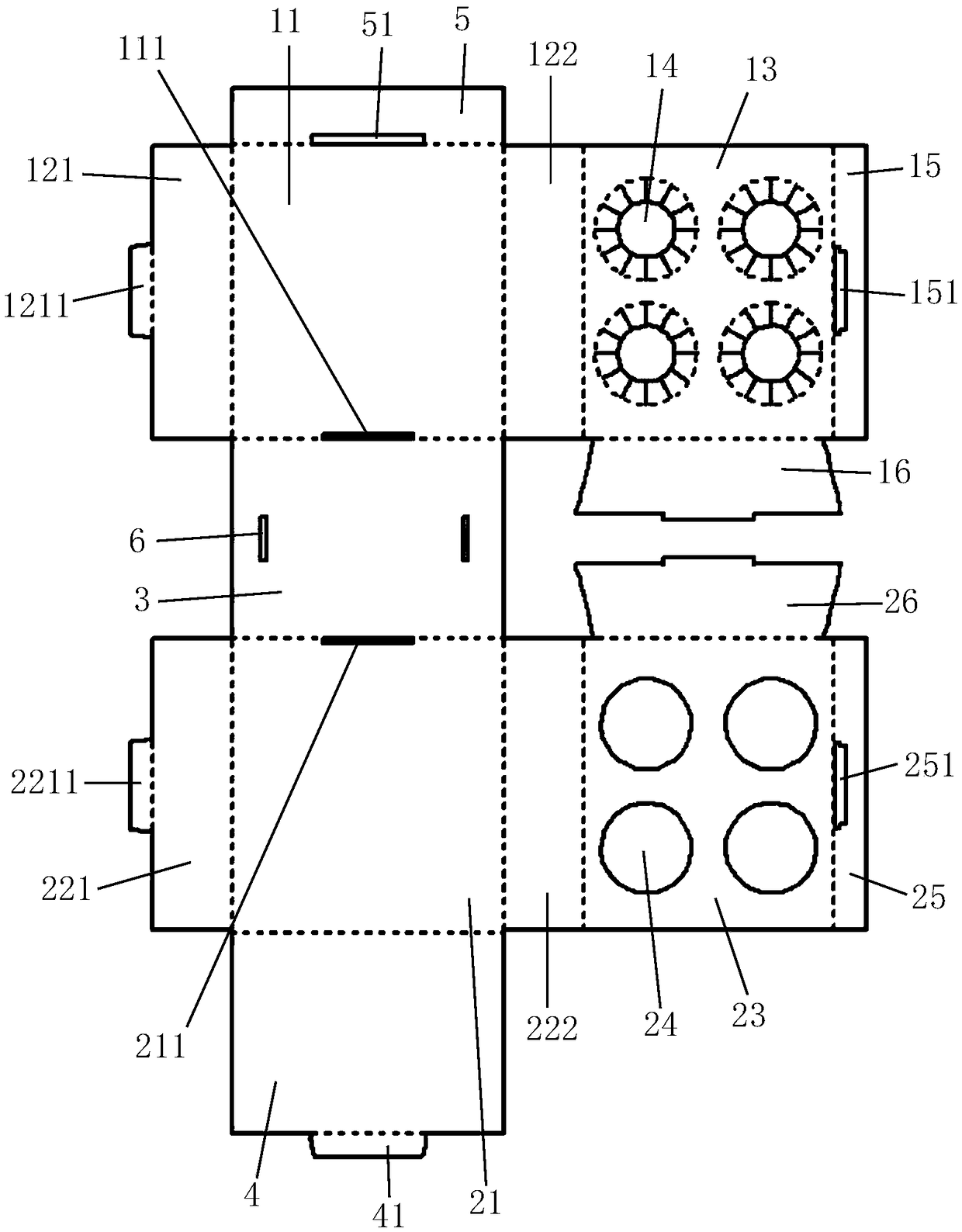
[0040] The board structure provided by this embodiment is as image 3 Shown, comprise upper cover plate 11, the first vertical plate 3 and lower cover plate 21, described upper cover plate 11, the first vertical plate 3 and lower cover plate 21 are longitudinally connected successively (the length direction of paper is longitudinal, the width direction is horizontal), the upper cover plate 11 and the lower cover plate 21 are respectively connected with the first bent plate 5 and the second vertical plate 4 by a fold line away from the side of the first vertical plate 3; the first bent plate 5 and the upper cover A first insertion seam 51 is provided at the connecting fold line of the board 11 , and a first insertion tongue 41 adapted to the first insertion seam 51 is connected to the fold line on the second vertical plate 4 .

[0041] In the unfolded panel structure, the two upper bearing panels 12 are the first side panel 121 and the second side panel 122 respectively, and th...

Embodiment 2

[0050] Such as Image 6 As shown, the plate body structure of this embodiment is roughly the same as that of Embodiment 1, the difference is that in this embodiment, positioning inserts 16 are connected with folding lines on both longitudinal sides of the upper support plate 13, and on the corresponding upper cover plate 11 The longitudinal connection fold line is provided with a positioning slot 111 adapted to the positioning insert 16, the positioning insert 26 is connected to the longitudinal both sides of the lower support plate 23 by a fold line, and the longitudinal connection fold line corresponding to the lower cover plate 21 is provided with a positioning slot 111. The positioning slot 211 that the insertion piece 26 is adapted to, when folded, the positioning insertion piece 16 is inserted into the corresponding positioning slot 111 , and the positioning insertion piece 26 is inserted into the corresponding positioning slot 211 .

[0051] Compared with Embodiment 1, ...

Embodiment 3

[0055] Such as Figure 7 As shown, the upper cover plate 11, the first vertical plate 3, the lower cover plate 21, the first bent plate 5, the second vertical plate 4, the first side plate 121, the second side plate 122, the second The structure of the three side plates 221 and the fourth side plate 222 and the connection relationship between them are roughly the same as in Embodiment 1, except that the shape and size of the first bent plate 5 in this embodiment are the same as those of the second vertical plate. 4 have the same shape and size, that is, after folding, the first bent plate 5 is attached to the inner side of the second vertical plate 4 and contacts the lower cover plate 21 to play a supporting role.

[0056] In addition, the upper support plate 13 in this embodiment includes a first upper support plate 131 connected to the first side plate 121 by a fold line, and a second upper support plate 132 connected to the second side plate 122 by a fold line, wherein the ...


PUM


Abstract

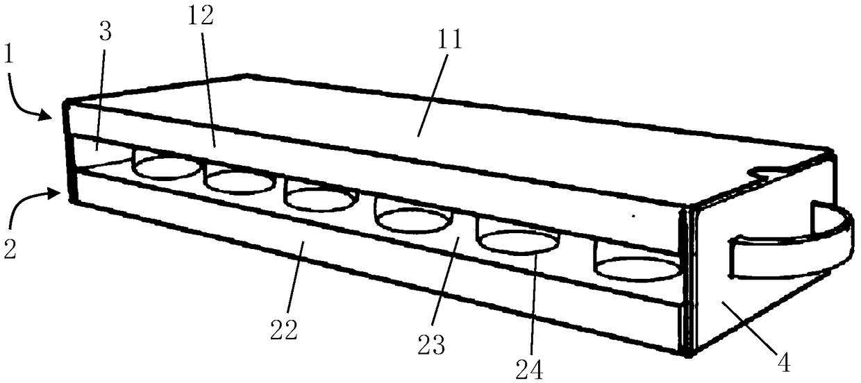
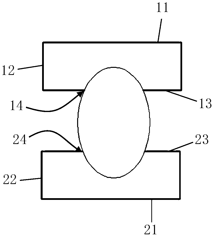
The invention relates to an anti-shock packaging box. The box comprises an upper supporting part and a lower supporting part; the upper supporting part comprises an upper cover plate, the two ends ofthe upper cover plate in the width direction are bent downwards to form upper bearing plates respectively, the bottoms of the two upper bearing plates are connected through an upper supporting plate,and multiple upper supporting holes are formed in the upper supporting plate; the lower supporting part comprises a lower cover plate, the two ends of the lower cover plate in the width direction arebent upwards to form lower bearing plates respectively, the tops of the two lower bearing plates are connected through a lower supporting plate, multiple lower supporting holes are formed in the lowersupporting plate, and the lower supporting holes correspond to the upper supporting holes one to one; gaps are reserved between the upper supporting plate and the upper cover plate as well as betweenthe upper supporting plate and the lower supporting plate as well as between the lower supporting plate and the lower cover plate; the two ends of the upper cover plate in the length direction are connected with the corresponding ends of the lower cover plate in the length direction through a first vertical plate and a second vertical plate respectively. According to the anti-shock packaging box,products are in a suspended state during transportation, and the box has good anti-shock performance.

Description

technical field [0001] The invention relates to the technical field of packaging supplies, in particular to an anti-shock packaging box. Background technique [0002] Nowadays, for the transportation of round fragile items (such as eggs, glass bottled liquid, etc.) or round items that are afraid of being squeezed (such as oranges and other fruits), foam boxes and plastic products are often used as fillers for packaging, or round plastic boxes are used. And the packaging method of foam tray, the former takes up space and is not environmentally friendly, while the latter has a complicated preparation process and poor shock resistance, which is prone to breakage or damage during transportation; in addition, the products of the above two transportation methods are packaged In the box, the appearance of the product in the box cannot be observed from the outside, and the display is poor. Contents of the invention [0003] Aiming at the defects in the prior art, the technical pr...

Claims


Application Information

Patent Timeline
Patent Type & Authority Applications(China)
IPC IPC(8): B65D5/50B65D85/30
CPCB65D5/50B65D85/30
Inventor 廖帆
Owner 成都玩创科技有限公司
Learn More