Adjustable siphon on drying cylinder

A siphon and adjustable technology, applied in the field of siphon, can solve problems such as inability to achieve the effect, and achieve the effect of the best siphon effect and simple structure

Active Publication Date: 2018-11-27
MUYANG XINKEDA QUARTZ PROD
View PDF6 Cites 0 Cited by
  • Summary
  • Abstract
  • Description
  • Claims
  • Application Information

AI Technical Summary

Problems solved by technology

The length of the existing siphon pipe extending from the drying cylinder to the inner surface of the drying cylinder is fixed, but the best effect cannot be achieved when actually siphoning the condensed water

Method used


Image

  • Adjustable siphon on drying cylinder
  • Adjustable siphon on drying cylinder
  • Adjustable siphon on drying cylinder

Examples


Embodiment Construction

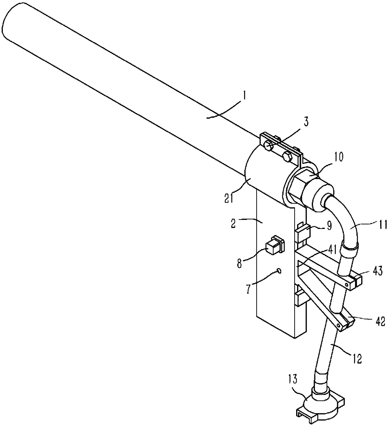
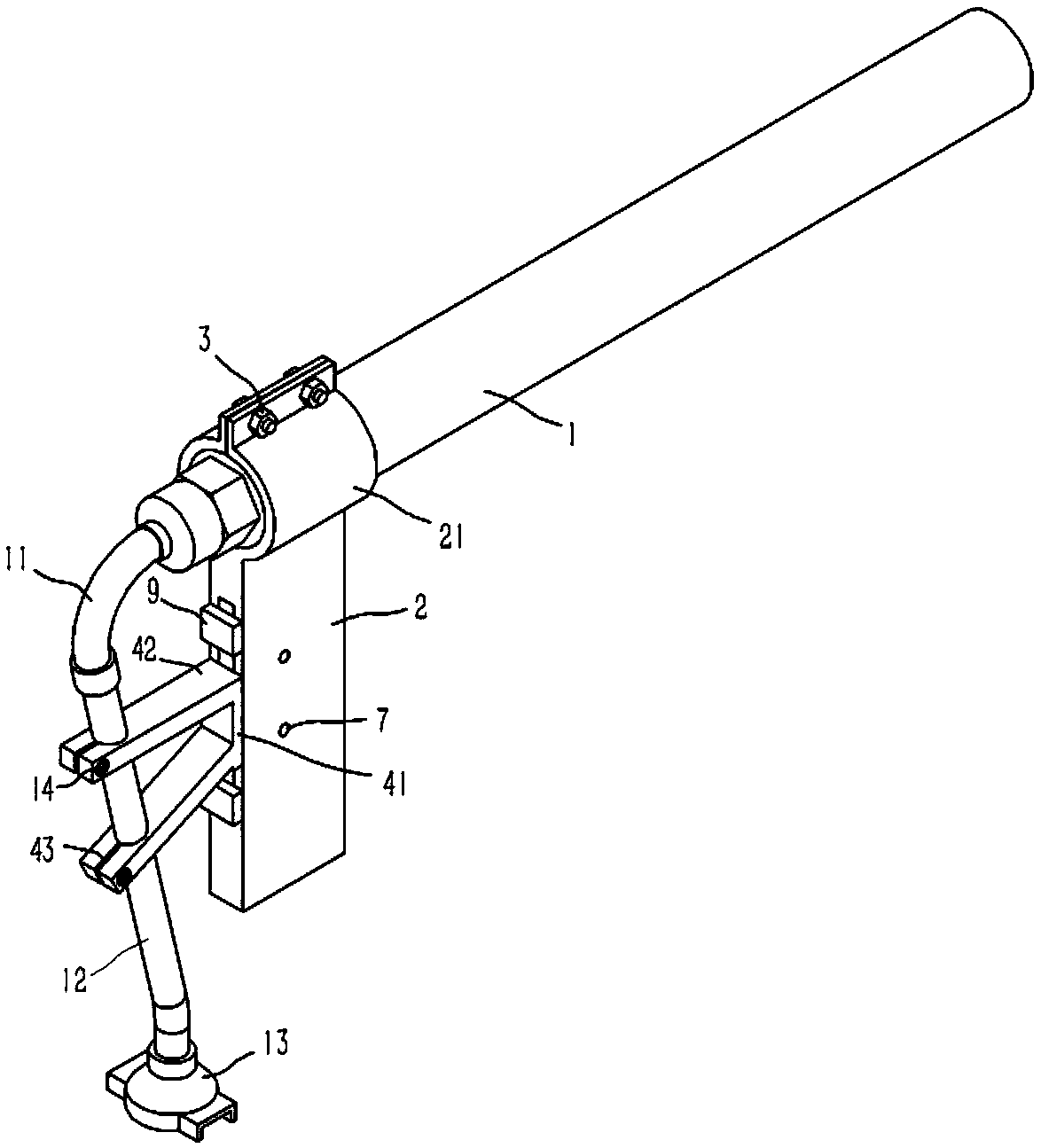
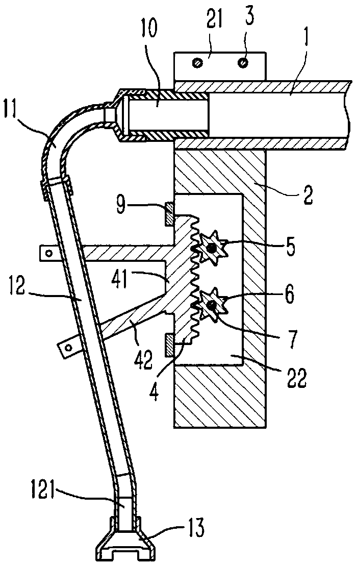
[0016] Example: see Figures 1 to 3 As shown, an adjustable siphon on a drying cylinder includes a horizontal main drain pipe 1, the inner end of the main drain pipe 1 is screwed with a connector 10, and the connector 10 is screwed with a metal hose 11, the metal hose The lower end of 11 is screwed with an inclined siphon pipe 12, and the lower end of the siphon pipe 12 is bent to form a vertical connecting pipe 121; An arc-shaped piece 21, the piece 21 is fixed on the main drainpipe 1 through the bolt assembly 3; the end surface of the fixed bracket 2 near the end of the siphon pipe 12 is formed with a slot 22, and the slot 22 of the fixed bracket 2 A vertical rack 4 is plugged in, the middle part of the rack 4 is formed with a baffle 41, the baffle 41 leans against the end face of the fixed bracket 2 near the end of the siphon tube 12, and the upper and lower ends of the slot 22 of the fixed bracket 2 are fixed with Block 9, block 9 leans against the upper and lower ends of...


PUM


Abstract

The invention discloses an adjustable siphon on a drying cylinder. The siphon comprises a horizontal main drain pipe, the inner side end of the main drain pipe is in screwed connection with a connecting head, the connecting head is in screwed connection with a metal hose, the lower end of the metal hose is in screwed connection with an inclined siphon body, and a vertical connecting pipe is bent and molded at the lower end of the siphon body; the lower side of the main drain pipe is provided with a fixing bracket, two arc-shaped pieces are formed on the upper end of the fixing bracket, and thepieces are fixed to the main drain pipe through a bolt assembly; a slot is formed in the end surface of the end, near one end of the siphon body, of the fixing bracket, a vertical rack is inserted into the slot of the fixing bracket, a baffle plate is formed in the middle of the rack, the baffle plate abuts the end surface of the end, near one end of the siphon body, of the fixing bracket, the upper and lower ends of the slot of the fixing bracket are fixed to stopping blocks, and the stopping blocks abut against the upper and lower ends of the rack. The siphon can achieve the precise fine adjustment of the spacing between the head of the siphon body and the inner surface of the drying cylinder so as to achieve the best siphon effect.

Description

Technical field: [0001] The invention relates to the technical field of drying cylinders, in particular to an adjustable siphon on the drying cylinders. Background technique: [0002] The drying cylinder is a hollow cylinder made of cast iron with covers at both ends, consisting of a cylinder body and cylinder covers at both ends. The cast iron dryer cylinder for paper machine is a key component for paper drying——Class I pressure vessel. The main components of the dryer cylinder include: roll shell, spoiler bar, siphon tube, end cover, manhole cover, bearing, shaft head, steam Connectors etc. The length of the existing siphon pipe extending from the drying cylinder to the inner surface of the drying cylinder is fixed, and the best effect cannot be achieved when actually siphoning the condensed water. Invention content: [0003] The purpose of the present invention is to provide an adjustable siphon on the drying cylinder, which can realize the precise fine-tuning of the ...

Claims


Application Information

Patent Timeline
Patent Type & Authority Applications(China)
IPC IPC(8): D21F5/10
CPCD21F5/10
Inventor 徐亚维
Owner MUYANG XINKEDA QUARTZ PROD
Why Eureka
Try Eureka