Cable telescopic device

A telescopic device and cable technology, applied in the direction of bridges, bridge parts, bridge construction, etc., to achieve the effect of simple structure, convenient installation and small external stress

Pending Publication Date: 2018-11-27
HENAN DASEN MECHANICAL & ELECTRICAL CO LTD
View PDF1 Cites 1 Cited by
  • Summary
  • Abstract
  • Description
  • Claims
  • Application Information

AI Technical Summary

Problems solved by technology

[0003] The purpose of the present invention is to provide a precise bridge cable telescopic device to solve the problem of compensating the cable due to the deformation of the bridge due to thermal expansion and contraction, so as to ensure the safety of the cable

Method used


Image

  • Cable telescopic device
  • Cable telescopic device
  • Cable telescopic device

Examples


Embodiment Construction

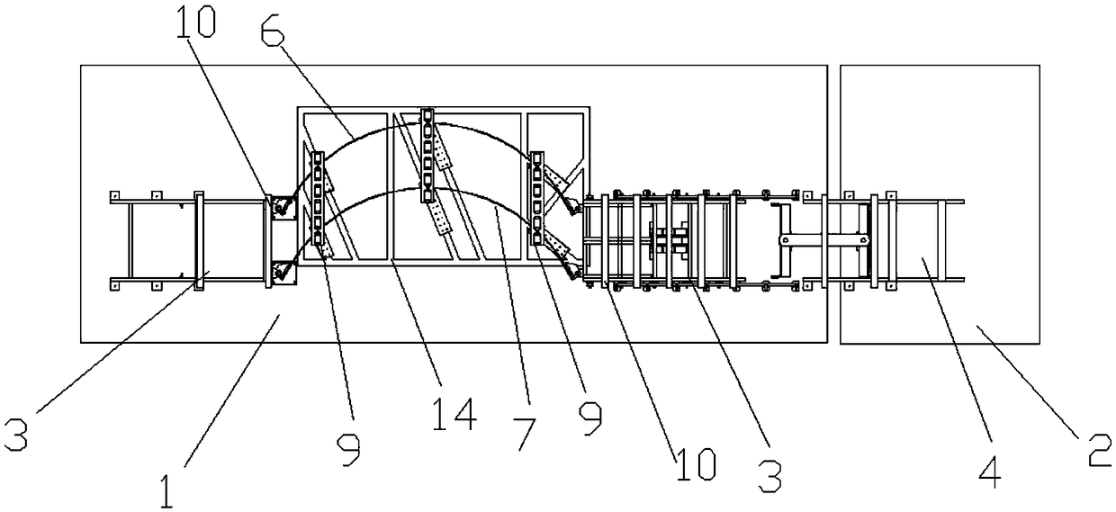
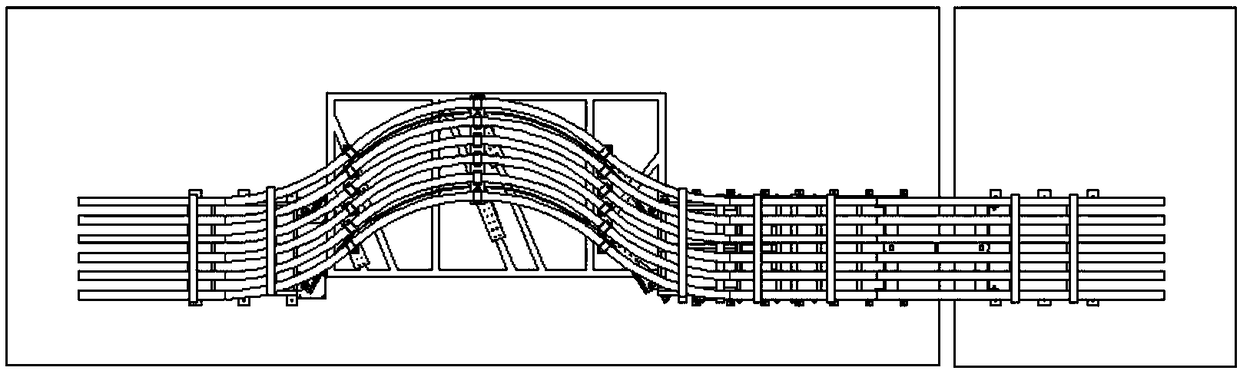
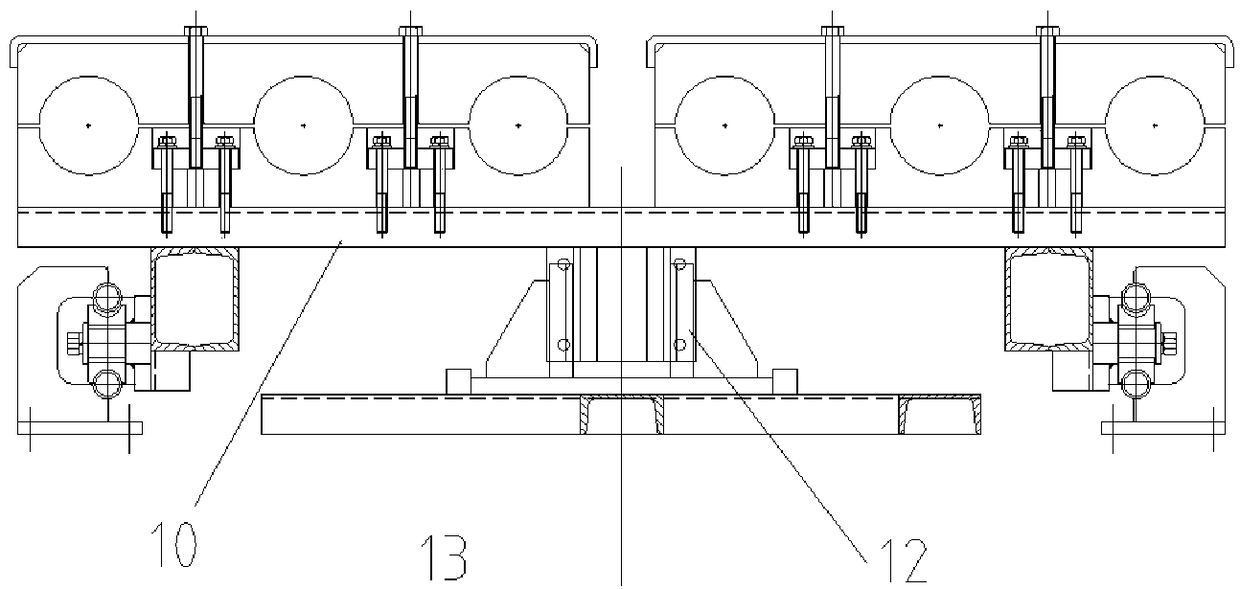
[0018] Such as Figure 1-Figure 3 Shown, the technical scheme that the present invention adopts is: bridge cable telescopic device, comprises fixed fixed mount 3, fixed hinge seat frame 4 and sliding trolley 5, and two fixed mounts are respectively fixed on two adjacent box girders, as figure 1 As shown, the fixed frame 3 is fixed on the box girder 1 on the left side, the fixed frame hinge frame 4 is fixed on the box beam 2 on the right side, and the sliding trolley 5 and the fixed hinge frame 3 are installed on the right side box girder. A guide mechanism is provided between the sliding trolley and the box girder. A universal knuckle mechanism is arranged between the fixed frame 3 and the sliding trolley 5 . One end of fixed frame hinge seat frame 4 and sliding dolly 5 is provided with hinge seat respectively, and this hinge seat is horizontal direction opening. A cable support structure is installed between the sliding trolley 5 and the fixed hinge seat frame 4, and the ca...


PUM


Abstract

The invention discloses a cable expansion and contraction device of a bridge, comprising a fixing frame, a fixing hinge seat frame and a sliding trolley. The fixing frame and the fixing hinge seat frame are respectively fixed on two adjacent box girders, and the sliding trolley and the fixing hinge seat frame are installed on the same box girder. Between that slide trolley and the fixed hinge seatframe, a cable support mechanism is arrange; The cable support mechanism comprises two spring steel plates; Three floating brackets are arranged between the upper ends of the two spring leaves; A plurality of rotary cable fixing clips are arranged on the floating bracket plate; The floating bracket plate is fixed on the spring steel plate through two splints and screws; The floating bracket plateand the splint are connected with a pin shaft; A connecting rod is respectively articulated with the lower end inner side of the two splints through a pin shaft; The fixing frame and the sliding trolley are respectively provided with cable fixing clips, and a guiding mechanism is arranged between the sliding trolley and the box girder.

Description

technical field [0001] The invention belongs to a mechanical movement device, in particular to a cable telescopic device inside a sea-crossing or river-crossing bridge. Background technique [0002] Due to the thermal expansion and contraction of the bridge itself and the influence of strong winds and waves from the outside, the gap between two adjacent box girders of the bridge will produce a certain relative displacement. When the displacement of the bridge exceeds a certain value, it will cause physical damage to the cables laid in the bridge, thus causing accidents. This requires designing a protective device for the cable to ensure that the cable can expand and contract according to the set trajectory. Although the published invention patent of CN201610257340 horizontally rotating cable expansion device can also realize the function of cable expansion and contraction, these inventions simply allow the cable to move and change with several sets of sector buffers of the ...

Claims


Application Information

Patent Timeline
Patent Type & Authority Applications(China)
IPC IPC(8): E01D19/10E01D19/00
CPCE01D19/10E01D19/00
Inventor 殷林杰张汉杰唐记敏陈书杰薛浩宋亚鹏
Owner HENAN DASEN MECHANICAL & ELECTRICAL CO LTD
Why Eureka
Try Eureka