Magnetic and Locking Cable Connectors

a technology of magnetic and locking cable and connector, which is applied in the direction of coupling device connection, selective content distribution, coupling device details, etc., to achieve the effect of enhancing connection quality, increasing and decreasing the exposure of data pins, and enhancing connection quality

Inactive Publication Date: 2011-06-09
PALLI CRAIG +2
View PDF10 Cites 40 Cited by
  • Summary
  • Abstract
  • Description
  • Claims
  • Application Information

AI Technical Summary

Benefits of technology

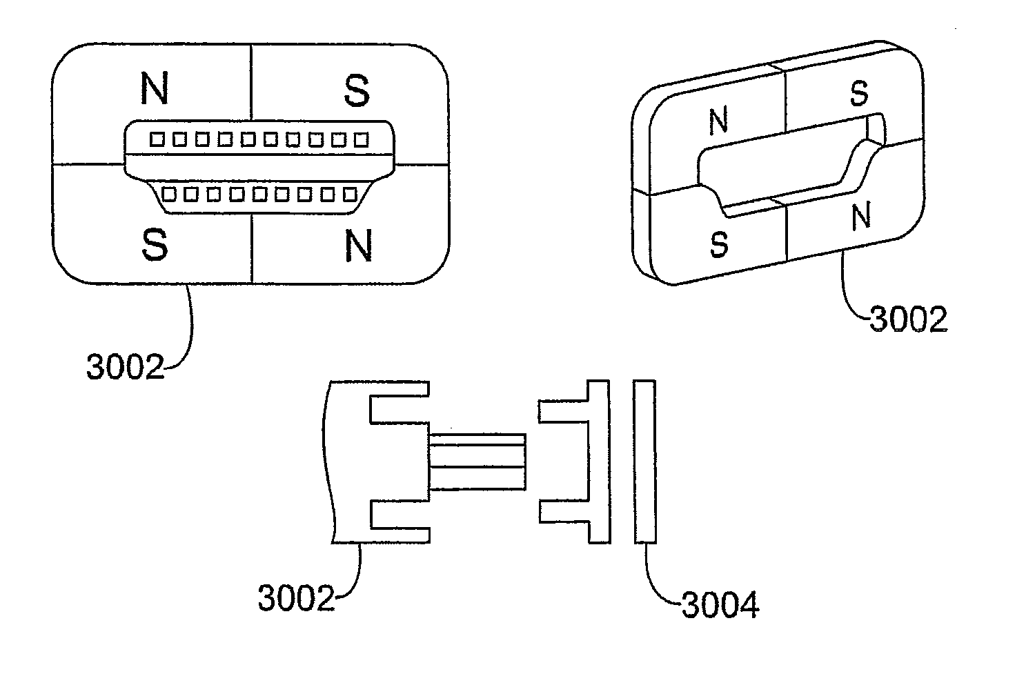
[0007]The various embodiments of the present invention provide a connector for optimizing magnetic force concentration, the connector comprising a plurality of magnets and a shunt plate arranged in the form of an array. The plurality of magnets may comprise a protrusion. Further, each recess of the plurality of recesses may be configured to receive a magnet of the plurality of magnets to form an array of magnets. Furthermore, the protrusion of the magnet may lock the magnet onto the recess.
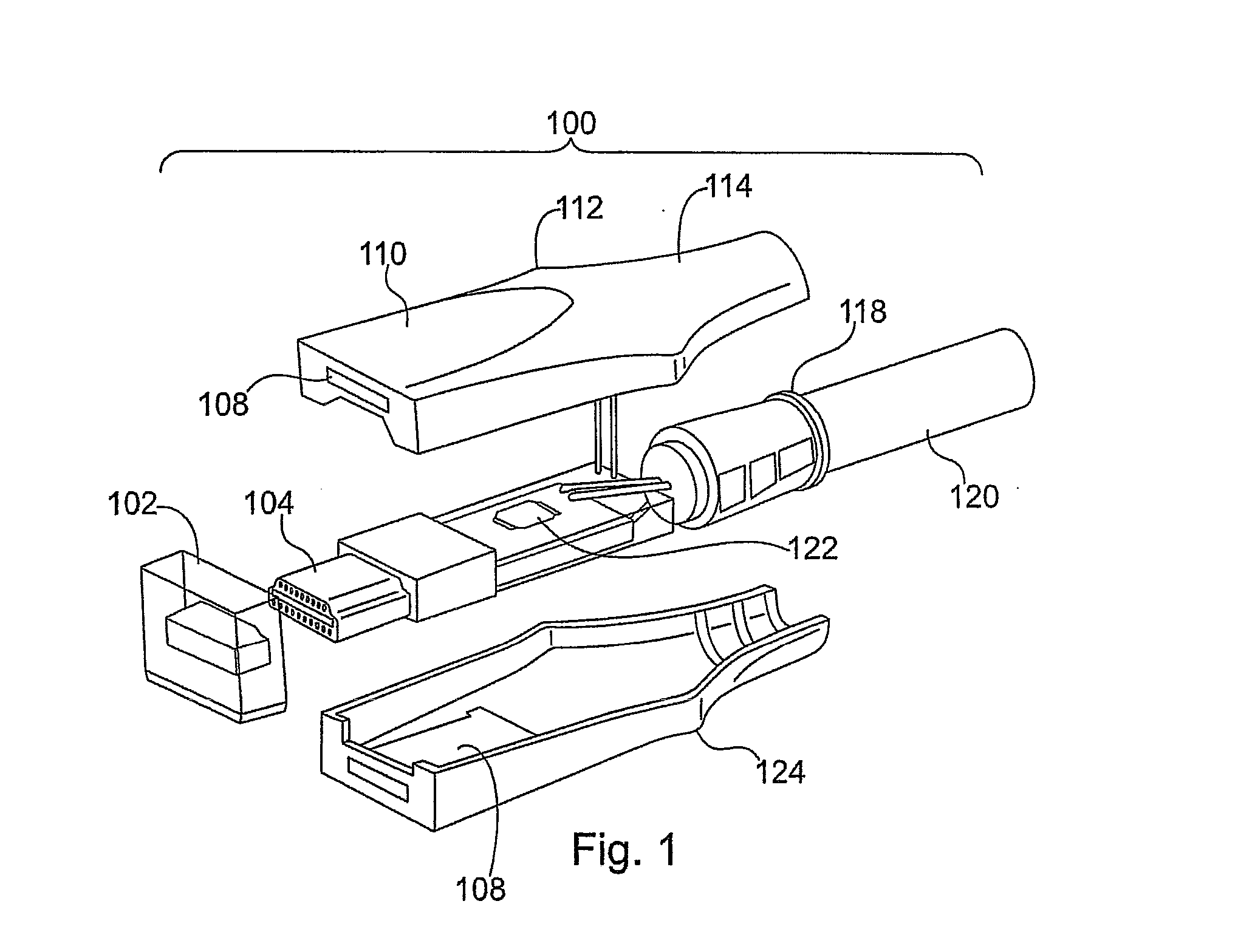
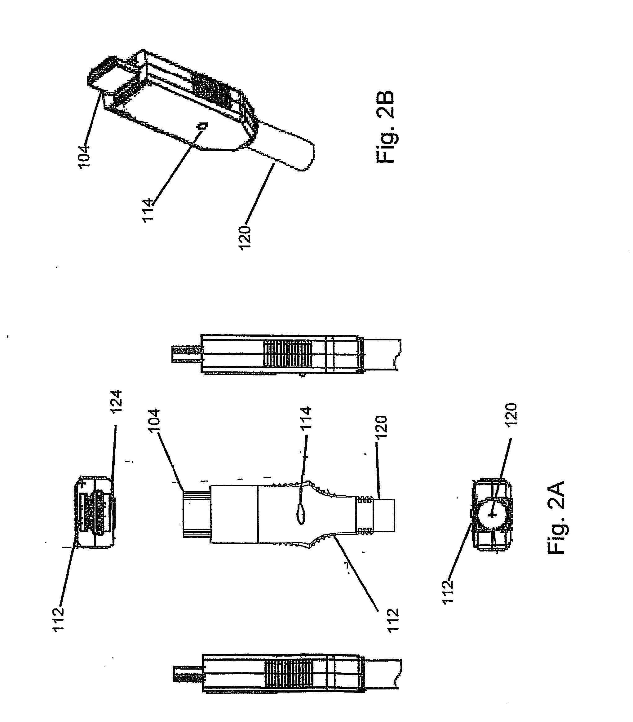
[0148]In embodiments, methods and systems for a device cable connector may be provided. The methods and systems may include a cable having a data transmission wire and a power wire, a device connector mechanically attached to the device connector end, a rigid pin alignment feature disposed within the device connector, and an electromagnet attached to the device connector and disposed to magnetically couple to at least one of a device and a device port. The cable may have a device connector end. The device connector may have at least one pin electrically associated with the data transmission wire and at least one pin electrically associated with the power wire. The device connector may have a slidable housing for enhanced connection quality. The slidable housing may slide to increase and decrease an exposure of a data pin of the device connector. The pins may be mounted in a resilient material which may allow the pins to flexibly move from side to side. The feature may have a guide hole through which the pins are aligned. The guide hole may be sized to allow the pins to flexibly move from side to side within a predetermined tolerance. The electromagnet may be powered by an electrical signal passed from the device port to the at least one pin electrically associated with the power wire.

Problems solved by technology

Furthermore, the protrusion of the magnet may lock the magnet onto the recess.

Method used


Image

  • Magnetic and Locking Cable Connectors
  • Magnetic and Locking Cable Connectors
  • Magnetic and Locking Cable Connectors

Examples


Embodiment Construction

)

[0214]Detailed embodiments of the present invention are disclosed herein; however, it is to be understood that the disclosed embodiments are merely exemplary of the invention, which can be embodied in various forms. Therefore, specific structural and functional details disclosed herein are not to be interpreted as limiting, but merely as a basis for the claims and as a representative basis for teaching one skilled in the art to variously employ the present invention in virtually any appropriately detailed structure. Further, the terms and phrases used herein are not intended to be limiting but rather to provide an understandable description of the invention.

[0215]The terms “a” or “an”, as used herein, are defined as one or more than one. The term “another”, as used herein, is defined as at least a second or more. The terms “including” and / or “having” as used herein, are defined as comprising (i.e. an open transition). The term “coupled” or “operatively coupled” as used herein, is d...


PUM

PropertyMeasurementUnit
lengthaaaaaaaaaa
sizeaaaaaaaaaa
thicknessaaaaaaaaaa

Abstract

In embodiments of the present invention improved capabilities are described for a cable connector. The cable connector may have magnetic properties and / or a locking mechanism. The cable connector may be an HDMI connector and the cable may be an HDMI cable. Further, the connector may be plugged into the corresponding male / female connector port and be held in position by the magnetic properties associated with the connector and the port and / or by a lock lever mechanism. The magnetic array may be moved various distances in various directions. In addition, the connector and / or cable may include a processor, an integrated circuit, an indicator, an LED and / or a user interface.

Description

CROSS-REFERENCE TO RELATED APPLICATIONS[0001]This application is a continuation of U.S. patent application Ser. No. 12 / 343,089 and claims the benefit of the following provisional applications, each of which is hereby incorporated by reference in its entirety: U.S. Provisional App. No. 61 / 016,535 filed Dec. 24, 2007; U.S. Provisional App. No. 61 / 029,519 filed Feb. 18, 2008; U.S. Provisional App. No. 61 / 033,072 filed Mar. 3, 2008; U.S. Provisional App. No. 61 / 057,044, filed May 29, 2008; and U.S. Provisional App. No. 61 / 108,719 filed Oct. 27, 2008.BACKGROUND OF THE INVENTION[0002]1. Field of the Invention[0003]The present invention relates to cable connectors for connecting different devices and, more particularly to magnetic and locking cable connectors.[0004]2. Description of the Related Art[0005]As the amount of information and data grows, so too does the number of devices and the interconnections between those devices. Current cabling technology for connection those devices is def...

Claims


Application Information

Patent Timeline
Patent Type & Authority Applications(United States)
IPC IPC(8): H01R11/30H01R43/00
CPCH01R13/504H01R13/6205Y10T29/49174H01R13/665H04N21/43635H01R13/6599
Inventor PALLI, CRAIGOSTERHOUT, RALPH F.HADDICK, JOHN
Owner PALLI CRAIG
Why Eureka
Try Eureka