
Bellows sleeve

A technology of corrugated pipes and pipe sleeves, which is applied in the direction of pipes/pipe joints/fittings, pipe laying and maintenance, mechanical equipment, etc., can solve the problems of corrugated pipe damage, time-consuming and laborious, etc., to avoid damage to corrugated pipes, improve installation accuracy and The effect of installation efficiency

Pending Publication Date: 2018-11-27
浙江康泰管业科技有限公司
View PDF0 Cites 0 Cited by
  • Summary
  • Abstract
  • Description
  • Claims
  • Application Information

AI Technical Summary

Problems solved by technology

This construction method is time-consuming and labor-intensive, and it is easy to cause damage to the bellows

Method used


Image

  • Bellows sleeve
  • Bellows sleeve
  • Bellows sleeve

Examples


Embodiment 1

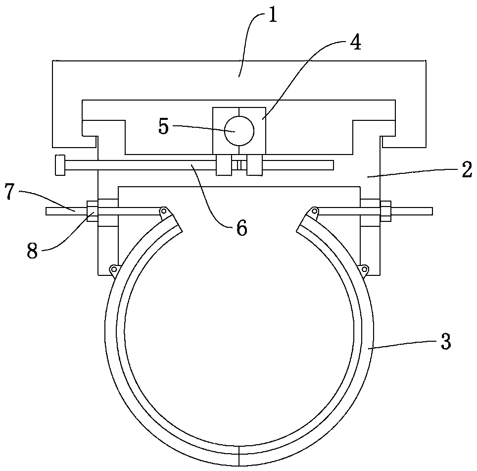
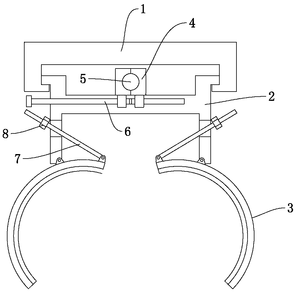
[0020] Embodiment 1: as figure 1 and figure 2 As shown, a bellows sleeve includes a bracket 1, a movable seat 2, and two arc-shaped sleeves 3 formed by buckling each other. The sleeves 3 are symmetrically distributed on the left and right sides of the center line of the bellows. The inner wall of the sleeve body 3 is provided with a clamping groove matching the crest of the bellows.

[0021] The sleeve body 3 is hinged on the movable seat 2 and rotates relative to the movable seat 2 in the radial direction of the bellows. The movable seat 2 is provided with a first control assembly for controlling the rotation of the sleeve body 3 to open or close the sleeve. The first control assembly includes a first screw rod 7 and an adjusting nut 8, and the movable base 2 is provided with a vertically arranged long slot, and the first screw rod 7 is inserted into the long slot, and the first screw rod 7 One end is hinged on the sleeve body 3, and the other end is screwed with an adjus...

Embodiment 2

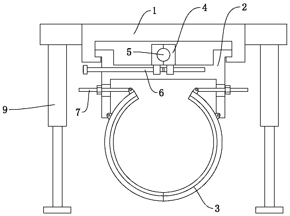
[0024] Embodiment 2: as image 3 As shown, the difference from Embodiment 1 is that support arms 9 are provided on the left and right sides of the bracket 1, and the support arms 9 are telescopic structures.

[0025] A method for using a bellows sleeve, comprising the following steps: 1) rotating the sleeve body 3 to fully open the two sleeve bodies 3; 2) inserting the bellows tube between the two sleeve bodies 3, and The sleeve body 3 is folded and clamped on the surface of the bellows to form a sleeve, and then the adjusting nut 8 is installed on the first screw 7 to fix the sleeve body at the corresponding position; The sleeve is raised to the corresponding height, so that the tube center of the clamped bellows is aligned with the tube center of the installed original tube; 4) Rotate the screw rod 5 through the handle, so that the movable seat 2 and the sleeve body 3 drive the bellows shaft Slowly insert the bellows into the socket of the original pipe to complete the inst...


PUM


Abstract

The invention relates to the technical field of bellows installation devices, in particular to a bellows sleeve. The bellows sleeve comprises a bracket, a movable seat and two arc sleeve bodies formedby mutual fastening. The sleeve bodies are symmetrically distributed on the left side and the right side of the center line of a bellows, the inner wall of each sleeve body is provided with a clamping groove matched the peak of the bellows. Each sleeve body is hinged on the movable seat and rotates in the bellows radial direction relative to the movable seat. The movable seat is provided with a first control assembly for controlling rotation of each sleeve body to open or close the sleeve. The movable seat is mounted on the bracket in the sliding mode, and the movable seat and the sleeve bodies move back and forth relative to the bracket in the bellows axial direction. The fixing and the positioning of the bellows are achieved by setting the movable sleeve bodies. The sleeve can assist the installation of the bellows, improve the installation precision and the installation efficiency and avoid damage to the bellows during the installation process.

Description

technical field [0001] The invention relates to the technical field of bellows installation equipment, in particular to a bellows sleeve. Background technique [0002] The installation and construction of the existing double-wall corrugated pipe generally adopts manual lowering of the pipe, and the two ends of the pipe body are tied with non-metallic ropes to keep the pipe body balanced and evenly slipped into the groove, and then the socket of the installed pipe is hung with ropes , another person inserts a long crowbar obliquely into the foundation, and presses against the transverse baffle at the center of the end of the pipe, and then slowly inserts the pipe into the socket of the original pipe to the predetermined position with force. This construction method is time-consuming and laborious, and it is easy to cause damage to the bellows. Contents of the invention [0003] The object of the present invention is to provide a bellows sleeve, which assists in the install...

Claims


Application Information

Patent Timeline
IPC IPC(8): F16L1/06F16L1/028
CPCF16L1/028F16L1/06
Inventor 潘明正李长辉盛颖杨金模张毅宋宇代兴民蹇胜强吴兴华
Owner 浙江康泰管业科技有限公司
Learn More