Eureka AIR delivers breakthrough ideas for toughest innovation challenges, trusted by R&D personnel around the world.

Oil discharging device

A technology of oil discharge device and protruding position, which is applied in the direction of connections with fluid cut-off devices, pipes/pipe joints/fittings, passing components, etc., which can solve the problem of slow oil discharge speed, reduce oil discharge time and improve Oil discharge efficiency and the effect of increasing the flow area

Pending Publication Date: 2018-11-27
CHANGSHA GREE HVAC EQUIP CO LTD +1
View PDF14 Cites 0 Cited by
  • Summary
  • Abstract
  • Description
  • Claims
  • Application Information

AI Technical Summary

Problems solved by technology

[0004] Therefore, the technical problem to be solved by the present invention is to overcome the defect of the slow oil discharge speed of the angle valve in the prior art, thereby providing an oil discharge device with a fast oil discharge speed

Method used


Image

  • Oil discharging device
  • Oil discharging device
  • Oil discharging device

Examples


Embodiment 1

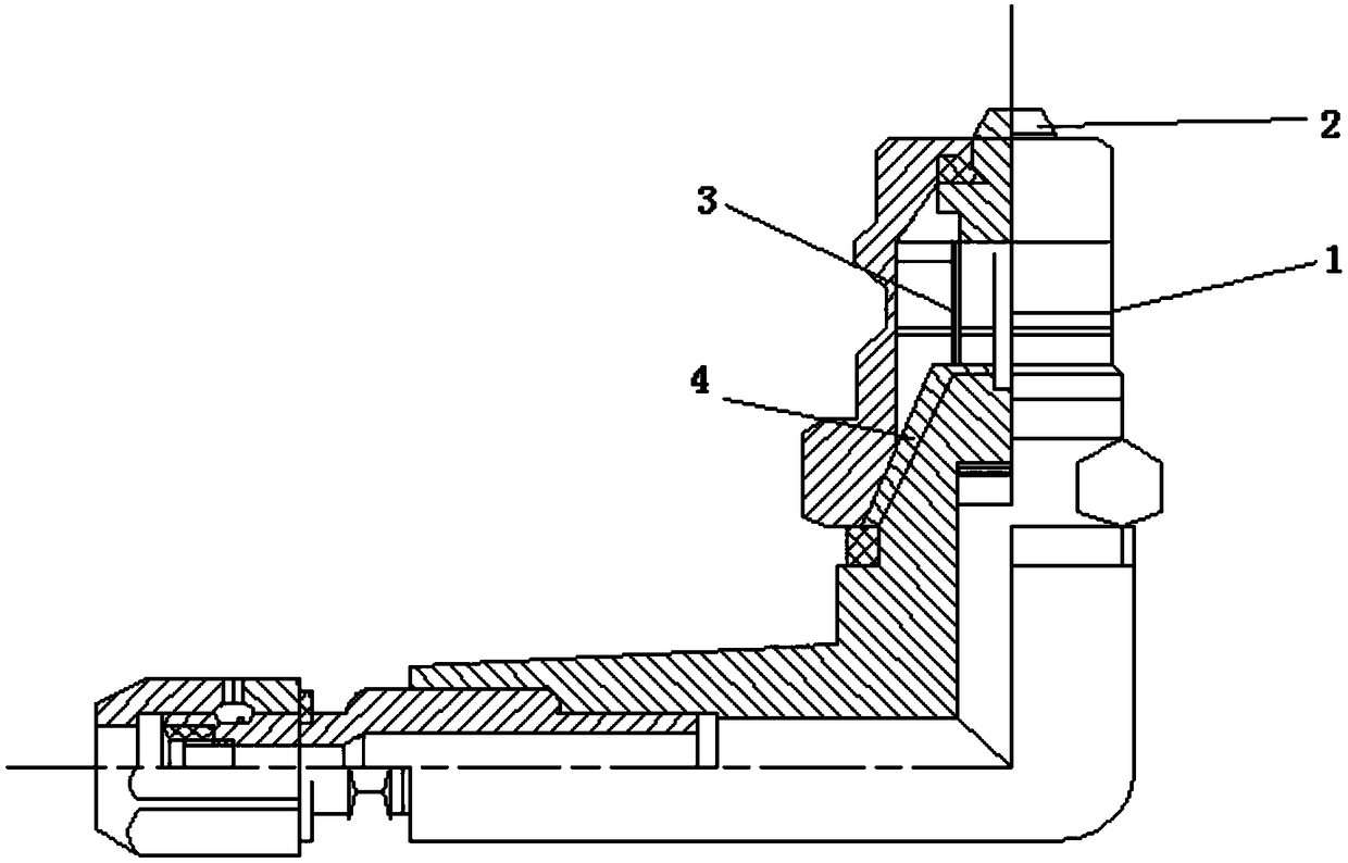
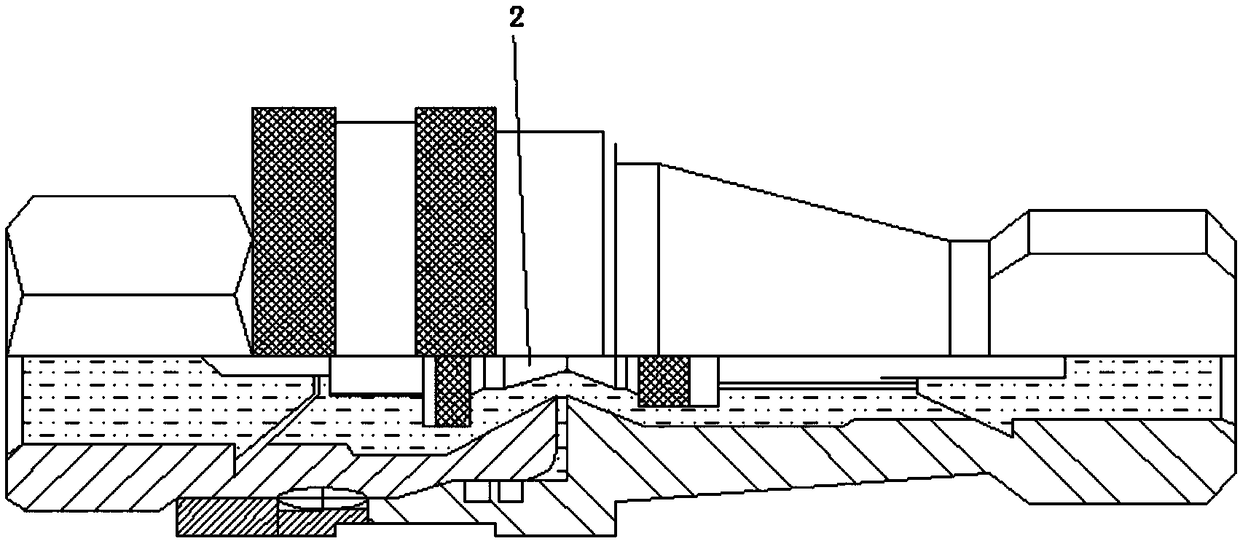
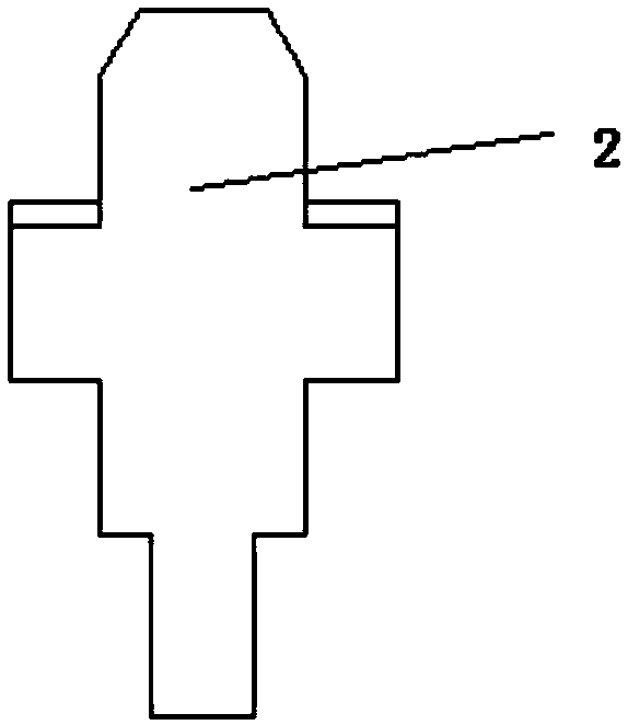
[0040] This embodiment provides an oil discharge device for discharging refrigerated oil and oil stains in a vacuum tube, comprising: a female joint sealingly connected with the vacuum pump tube, and a male joint that can be butted with the female joint. The female connector in this embodiment is as figure 1 As shown, the female joint includes a female joint housing 1, a first valve core 2, and a first biasing member 3. The female joint housing 1 has a first through cavity, and the first valve core 2 can be A retracted position and a first protruding position are set in the first through cavity so as to move, and the biasing force of the first biasing member 3 acts on the first valve core 2, so that the first A valve core 2 is in the first biasing member 3 of the first extended position, and when the first valve core 2 is in the first extended position, it forms a seal with the first through cavity, and the first When the spool 2 moves to the first retracted position under t...


PUM


Abstract

The invention provides an oil discharging device which includes a female joint and a male joint, wherein the female joint is in sealing connection with a vacuum pump pipe and includes a female joint casing with a first through chamber, a first valve core capable of being movably arranged in the first through chamber between a first retraction position and a first extending-out position, and a first bias pressure part, wherein a bias pressure of the first bias pressure part acts on the first valve core to make the first valve core at a first extending-out position, and when the first valve coreis at the first extending-out position, a seal is formed between the first valve core and the first through chamber; and under the action of an external force, when the first valve core moves to thefirst retraction position, a circulating gap is formed between the first valve core and the first through chamber. The male joint can be in butt joint with the female joint and includes a male joint casing with a second through chamber and an abutting portion disposed on the male joint casing. During butt joint, the abutting portion abuts against a head portion of the first valve core to make thehead portion move to the first retraction position, so that the first through chamber is communicated with the second through chamber; the cross section area of the abutting portion is smaller than that of the head portion of the first valve core, and the oil discharging speed is quick.

Description

technical field [0001] The invention relates to the technical field of vacuum hose oil discharge, in particular to an oil discharge device. Background technique [0002] When moisture and air remain in the refrigeration system, it will cause great harm to the air-conditioning system: when the refrigeration temperature falls below 0°C, the water will freeze, causing ice blockage in the narrow pipes of the air-conditioning system; Metals have corrosion hazards; promote the oxidation of refrigerants and lubricating oils; if there is too much air, the system airflow will not be smooth, affecting the refrigerant steam flow, system pressure, and even the composition of the refrigerant, resulting in a decline in the performance of the refrigeration system. Therefore, the refrigeration system Before filling the refrigerant, the non-condensable gas in the system must be removed to make the vacuum degree meet the process requirements. A vacuum pump is a special device for extracting ...

Claims


Application Information

Patent Timeline
Patent Type & Authority Applications(China)
IPC IPC(8): F16L37/44F16L29/02
CPCF16L29/02F16L37/44
Inventor 肖卫星王晓彬周锴古湘龙罗超丁振华王盛国
Owner CHANGSHA GREE HVAC EQUIP CO LTD
Why Eureka
Eureka Blog
Learn More