Impact resistance testing device for production of wooden packaging box

A testing device and packaging box technology, applied in the direction of measuring devices, instruments, scientific instruments, etc., can solve the problems such as affecting the test results, not being able to limit the position of the packaging boxes of different sizes, and not being able to effectively prevent secondary impacts, etc., to achieve practicability Strong, easy-to-fix effect

Pending Publication Date: 2018-11-27
江苏佳诚包装材料有限公司
View PDF7 Cites 3 Cited by
  • Summary
  • Abstract
  • Description
  • Claims
  • Application Information

AI Technical Summary

Problems solved by technology

[0002] Wooden packaging materials are easy to obtain and are environmentally friendly. During the production of wooden packaging boxes, impact resistance tests on wooden panels are re

Method used


Image

  • Impact resistance testing device for production of wooden packaging box
  • Impact resistance testing device for production of wooden packaging box

Examples


Embodiment 1

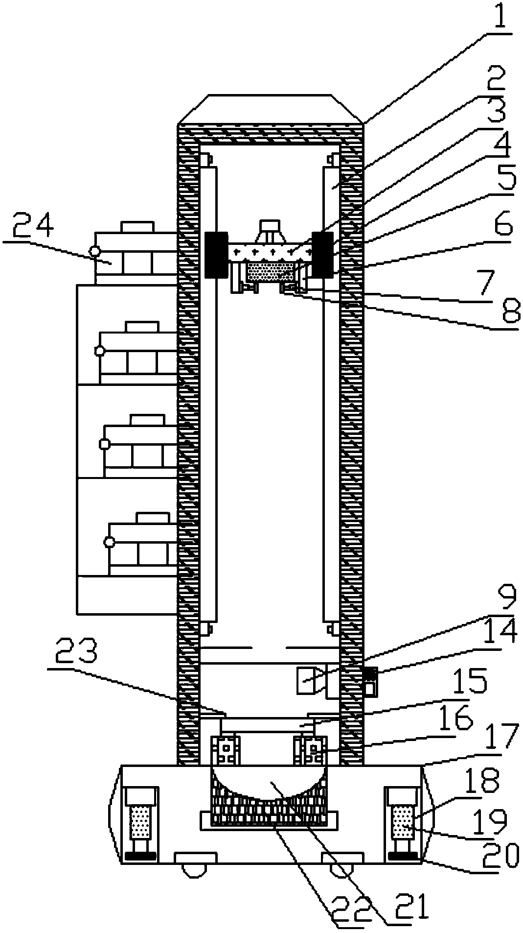
[0024] Such as Figure 1-2 As shown, a kind of impact resistance test device for the production of wooden packaging boxes includes a U-shaped bracket 1 and a base 17. The two ends of the base 17 are provided with installation cavities 18, and the top of the installation cavity 18 is provided with a No. Electric hydraulic cylinder 19, the output shaft of the No. 1 electric hydraulic cylinder 19 is equipped with a support pad 20 through a screw, the top of the base 17 is equipped with a U-shaped support 1 through a bolt, and the bottom end of the U-shaped support 1 is a The side is provided with a gravity sensor switch 14 through the installation groove, and the two sides of the inner wall of the U-shaped bracket 1 are installed with electric slide rails 2 through screws, and a No. A connecting rod 3 is arranged on the butt joint, and a No. 1 electromagnetic chuck 5 is installed on the connecting rod 3 through a mounting groove. The two ends of the bottom of the connecting rod 3...

Embodiment 2

[0033] Such as Figure 1-2 As shown, a kind of impact resistance test device for the production of wooden packaging boxes includes a U-shaped bracket 1 and a base 17. The two ends of the base 17 are provided with installation cavities 18, and the top of the installation cavity 18 is provided with a No. Electric hydraulic cylinder 19, the output shaft of the No. 1 electric hydraulic cylinder 19 is equipped with a support pad 20 through a screw, the top of the base 17 is equipped with a U-shaped support 1 through a bolt, and the bottom end of the U-shaped support 1 is a The side is provided with a gravity sensor switch 14 through the installation groove, and the two sides of the inner wall of the U-shaped bracket 1 are installed with electric slide rails 2 through screws, and a No. A connecting rod 3 is arranged on the butt joint, and a No. 1 electromagnetic chuck 5 is installed on the connecting rod 3 through a mounting groove. The two ends of the bottom of the connecting rod 3...


PUM


Abstract

The invention discloses an impact resistance testing device for production of a wooden packaging box. The device comprises a U-shaped rack and a base, mounting cavities are formed in the two ends of the base, and a first electric hydraulic cylinder is arranged at the top in each mounting cavity through a mounting plate; a supporting cushion block is installed on the output shaft of each first electric hydraulic cylinder through screws, the U-shaped rack is installed at the top of the base through bolts, and a gravity sensing switch is arranged at one side of the bottom of the U-shaped rack through a mounting groove; electric sliding rails are mounted at the two sides of the inner wall of the U-shaped rack through screws, first sliding blocks are arranged in the electric sliding rails, anda connection rod is arranged between the first sliding blocks through a butt joint sheet; a first electromagnetic suction cup is installed on the connection rod through a mounting groove, and electricpush rods are connected to the two ends of the bottom of the connection rod through supporting rods. According to the impact resistance testing device, packaging box boards different in size are conveniently limited and subjected to impact resistance testing, second impact is effectively prevented, and the device is high in practicability and suitable for wide popularization.

Description

technical field [0001] The invention relates to the technical field of testing equipment, in particular to an impact resistance testing device for the production of wooden packaging boxes. Background technique [0002] Wooden packaging materials are easy to obtain and are environmentally friendly. During the production of wooden packaging boxes, impact resistance tests on wooden panels are required. However, the existing testers cannot limit the spacing of packaging box panels of different sizes, and cannot effectively prevent secondary impact, affecting the test results. For this reason, we propose an impact resistance test device for the production of wooden packaging boxes. Contents of the invention [0003] The main purpose of the present invention is to provide an impact resistance test device for the production of wooden packaging boxes. The packaging box plate is placed in the limit groove inside the extrusion plate, and the extrusion plate is driven to the middle ...

Claims


Application Information

Patent Timeline
IPC IPC(8): G01N3/303G01N3/02G01N3/04
CPCG01N3/02G01N3/04G01N3/303G01N2203/001G01N2203/0033
Inventor 孙国成施小红
Owner 江苏佳诚包装材料有限公司
Why Eureka
Try Eureka