Double-precision optical regulation transmission device

A transmission device and optical adjustment technology, applied in optics, optical components, instruments, etc., can solve the problems of interference efficiency adjustment, harmful effects of beam alignment adjustment, and low adjustment efficiency, so as to improve adjustment stability and increase adjustment efficiency Effect

Inactive Publication Date: 2018-11-27
安徽至博光电科技股份有限公司
View PDF0 Cites 2 Cited by
  • Summary
  • Abstract
  • Description
  • Claims
  • Application Information

AI Technical Summary

Problems solved by technology

[0005] Usually, the tooth pitch of the fine-tooth screw is fixed, such as 0.25mm, 0.2mm; when the adjustment stroke is large, when the fine-tooth screw is screwed in or out to a large depth, it is necessary to continuously rotate the fine-tooth screw for multiple turns to reach the predetermined position , and then fine-tuned, the adjustment efficiency is low
[0006] At the same time, when the fine tooth screw is rotated for adjustment, the ball head at the top of the fine tooth screw is continuously rotating while moving forward or backward, and there is shear between the ball head at the top of the fine tooth screw and the limit structure on the transmission part. Friction, the rotational movement will make the transmission part swing, although the swing amplitude is very small, it is harmful to the adjustment of precision optical path, such as the adjustment of interference efficiency in the interference optical path, and the adjustment of beam alignment

Method used


Image

  • Double-precision optical regulation transmission device
  • Double-precision optical regulation transmission device
  • Double-precision optical regulation transmission device

Examples


Embodiment Construction

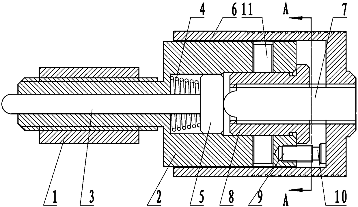
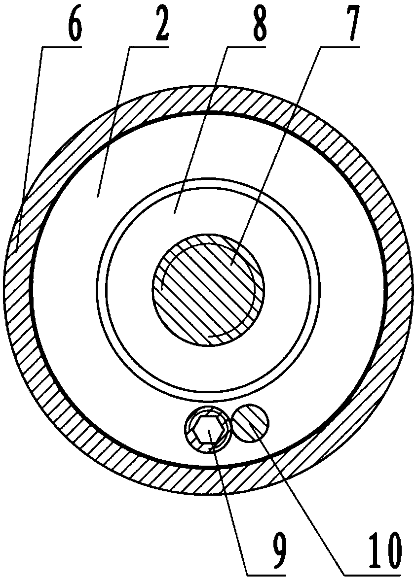
[0020] see figure 2 And and 3, the double-precision optical adjustment transmission device of the present invention includes a coarse-threaded nut 1 fixed on the optical adjustment frame and a coarse-threaded screw 2 threadedly connected with the coarse-threaded nut 1 .

[0021] The described coarse tooth screw 2 is provided with a center hole along its axial direction, and a ball head polished rod 3 that is a ball head is installed in the center hole in a moving fit. The other end of the head expands into a chamber, and the chamber is provided with a compression spring 4, a slider 5 and a fine thread nut 8 in sequence along the ball head direction away from the polished rod 3 of the ball head; wherein, the compression spring 4 wears Located outside the polished ball rod 3, the slider 8 is connected to the polished rod 3, and the fine thread nut 8 and the coarse thread screw 2 are in contact with each other, and two anti-slip screws 11 are provided to prevent slippage. Screw...


PUM


Abstract

The invention relates to an installing and regulating device of an optical element, system or instrument, in particular to a double-precision optical regulation transmission device. The installing andregulating device comprises a coarse thread screw nut fixed on an optical regulating frame and a coarse thread screw rod connected through screw threads; the coarse thread screw rod is provided witha center hole in the axial direction; a ball head polish rod with a ball head at one end is arranged in the center hole; the center hole forms a cavity through expansion at the other end of the ball head; a press spring arranged outside the ball head polish rod in a penetrating way, a slide block connected with the ball head polish rod and a fine thread screw nut are sequentially arranged in the cavity; the fine thread screw nut is connected with a fine thread screw rod with one ball-shaped end through screw threads; the ball head of the fine thread screw rod is connected with the slide block;the other end is concentric with the regulation handle is fixed on the regulating handle; a position limiting post is fixedly arranged on the end surface of one end, near the regulating handle, of the coarse thread screw rod; a transmission post is fixedly arranged on the end surface, near the coarse thread screw rod, of the regulating handle. The installing and regulating device has the advantages that the coarse regulation and fine regulation double-precision regulation function can be realized; the higher regulation efficiency is improved; the light spot jumping in the regulation process is small; the light beams can be easily aligned.

Description

technical field [0001] The invention relates to an installation and adjustment device of an optical element, system or instrument, in particular to a double-precision optical adjustment transmission device. Background technique [0002] At present, the known precision optical adjustment mount (see attached figure 1 ) includes two functions of angle adjustment and translation adjustment, figure 1 Shown is a general-purpose solution for the two-dimensional angle adjustment frame, which mainly includes several parts shown in the figure. The fixed plate is generally fixed on the equipment through the installation hole. When adjusting one dimension rotation, by rotating one of the thread pairs, the thread The auxiliary nut is fixed on the fixed plate. The front end of the threaded auxiliary screw is a hemisphere. When the threaded auxiliary screw is rotated, the threaded auxiliary screw moves forward while rotating, pushing the movable plate to rotate around the supporting steel...

Claims


Application Information

Patent Timeline
Patent Type & Authority Applications(China)
IPC IPC(8): G02B27/62
CPCG02B27/62
Inventor 汪辉郝文良程建民刘文静
Owner 安徽至博光电科技股份有限公司
Why Eureka
Try Eureka