Mold regulator of powder molding machine

An adjustment device and a technology of a compression molding machine, applied in the field of machinery, can solve the problems affecting the stability of use, unilateral force on the core rod sleeve, time-consuming and labor-intensive, etc., and achieve the effects of high adjustment stability, balanced force, and easy adjustment.

Inactive Publication Date: 2011-10-19
苏光宝
View PDF6 Cites 0 Cited by
  • Summary
  • Abstract
  • Description
  • Claims
  • Application Information

AI Technical Summary

Problems solved by technology

[0005] However, since the screw is located at the bottom of the mold seat, the space at the bottom of the mold seat is narrow, which makes it very inconvenient during the adjustment process.
At the same time, there must be at least two screws. If a single screw is used, it will cause one-sided stress on the core rod sleeve, which will affect its stability in use.
It can be seen that since there are many screws, the adjustment is cumbersome, time-consuming and labor-intensive

Method used


Image

  • Mold regulator of powder molding machine
  • Mold regulator of powder molding machine
  • Mold regulator of powder molding machine

Examples


Embodiment 1

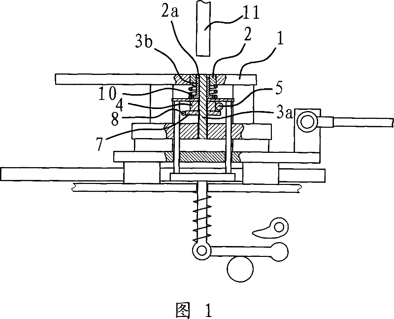
[0030] Such as figure 1 As shown, the powder compression molding machine includes a mold arranged on a frame and a stamping head 11 located above the mold, and the mold adjustment device of the powder compression molding machine is arranged at the mold.

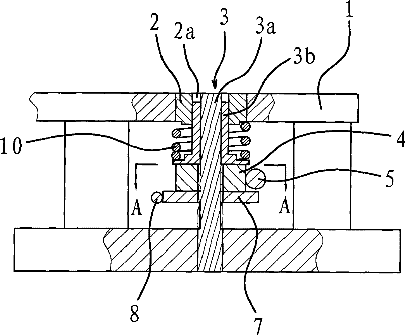
[0031] The mold of the powder compression molding machine is composed of a mold base 1, a storage body 2 and a stripping body 3, etc. Wherein, the material storage body 2 is fixedly connected to the mold base 1, and the material storage body 2 is provided with a material hole 2a passing through it up and down.

[0032] The stripping body 3 is composed of a core rod 3a and a core rod sleeve 3b, the core rod 3a is cylindrical, and the outer diameter of the core rod 3a is smaller than the diameter of the material hole 2a. The core rod sleeve 3b is cylindrical, the outer diameter of the core rod sleeve 3b is slightly smaller than the diameter of the material hole 2a, and the inner diameter of the core rod sleeve 3b is slightly l...

Embodiment 2

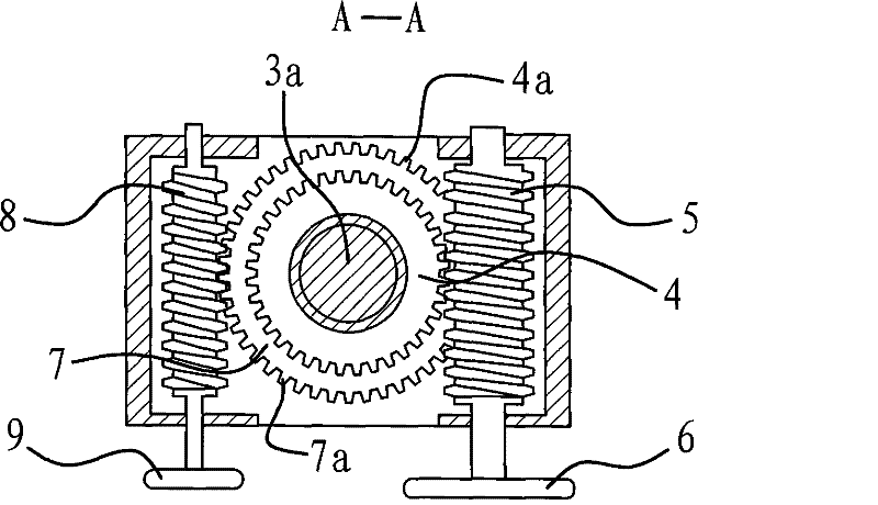
[0042] The structure and principle of this embodiment are basically the same as that of Embodiment 1, the difference is that the rotating structure is a prismatic structure on the outside of the regulating body 4, see Figure 4 and Figure 5 shown. When the adjusting body 4 needs to be rotated, a tool such as a wrench is connected to the prismatic place of the adjusting body 4, and the wrench can be pulled to drive the adjusting body 4 to rotate.

[0043] At the same time, in this embodiment, the locking structure is a prismatic structure outside the locking body 7, see Figure 4 and Figure 5 shown. When the locking body 7 needs to be rotated, a tool such as a wrench is connected to the prismatic place of the locking body 7, and the locking body 7 can be driven to rotate by pulling the wrench.


PUM


Abstract

The present invention provides one kind of mold regulator of powder molding machine, and belongs to the field of mechanical technology. The mold regulator set near the mold includes one mold seat, one material storing unit connected to the mold seat and with material hole, and one material discharging unit comprising one circular core rod and one cylindrical sleeve, and one regulating unit aroundthe middle part of the core rod. The mold regulator has the advantages of simple operation, easy regulation and high stability.

Description

technical field [0001] The invention belongs to the technical field of machinery, and relates to a powder compression molding machine, in particular to a mold adjusting device of a powder compression molding machine which uses polytetrafluoroethylene powder raw materials to press workpieces. Background technique [0002] The workpiece made of polytetrafluoroethylene powder die-casting has simple manufacturing process and low manufacturing cost. Therefore, powder compression molding machines are widely used in machining. Generally, a powder compression molding machine includes a mold and a stamping head located on the upper part of the mold, and the powder raw material at the mold can be pressed into shape by pressing down the stamping head. [0003] The mold of an existing powder compression molding machine is composed of a mold base, a material storage body and a stripping body. It consists of a core rod connected to the mold base and a core rod sleeve sleeved on the core...

Claims


Application Information

Patent Timeline
Patent Type & Authority Patents(China)
IPC IPC(8): B30B15/02
Inventor 苏光宝
Owner 苏光宝
Why Eureka
Try Eureka