A flip-type lifting device for a computer monitor and a multifunctional computer table
A lifting device and display technology, which is applied to desks, computer workstation tables or desks, household appliances, etc., can solve the problems of low degree of automation, inconvenient installation and debugging of monitor lifting tables, etc., achieve high degree of automation, facilitate teaching applications, The effect of avoiding short-circuit problems
- Summary
- Abstract
- Description
- Claims
- Application Information
AI Technical Summary
Problems solved by technology
Method used
Image
Examples
Embodiment 1
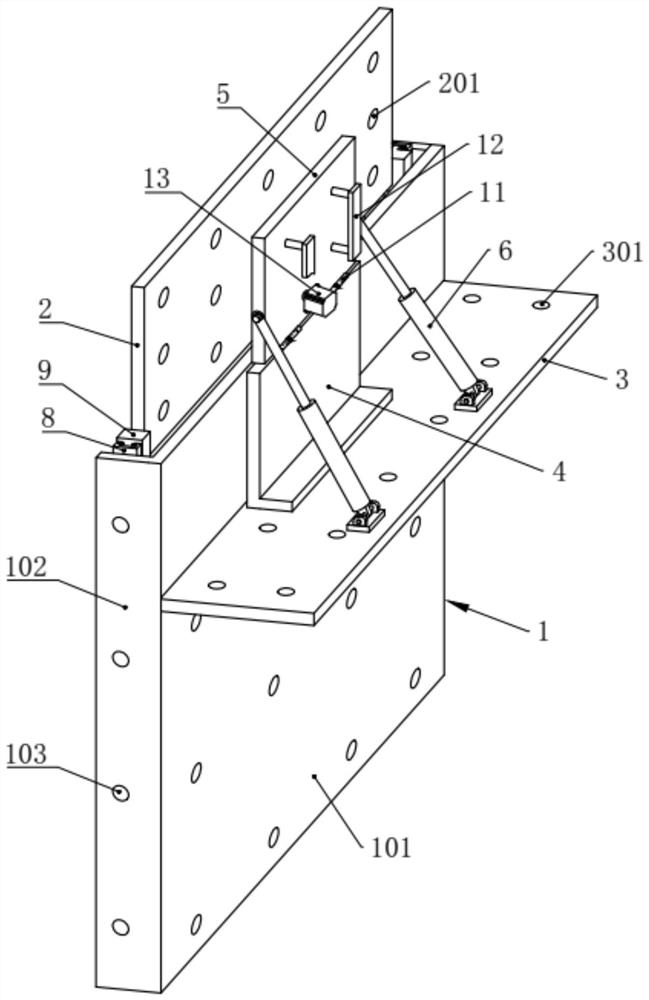
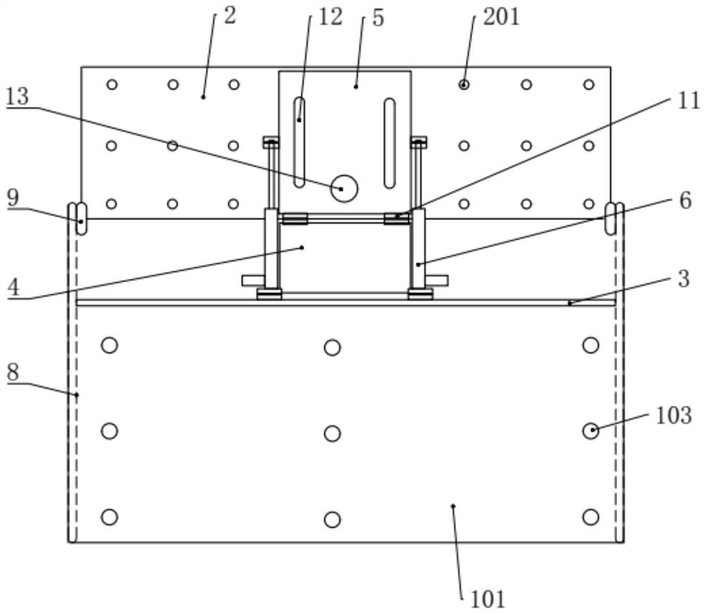
[0041] like Figure 1 to 4 As shown, the present embodiment provides a computer display flipping lifting device, including the mounting substrate 1, the mounting substrate 1 slides on the installed on the desktop fixing plate 2, the desktop fixing plate 2 is used to mount the desktop 23, and on the desktop The fixing plate 2 is hinged to the mounting substrate 1, and the mounting substrate 1 is also fixed to fix the lower desktop fixing plate 3, and the lower desktop fixing plate 3 is used to mount the desktop 24, and the lower desktop fixing plate 3 is hinged by the support plate 4 The display mounting plate 5, the display mounting plate 5 is provided with the upper desktop fixing plate 2 to implement the upper and lower sliding mechanisms on the upper desktop fixing plate 2, and the display mounting plate 5 and the lower desktop fixing plate 3 are provided with the display mounting plate. 5 Remote electric telescopic rod 6.
[0042] Both ends of the mounting substrate 1 are provi...
Embodiment 2
[0056] like Figure 12 with Figure 13 In the same manner as the embodiment of the embodiment, the present embodiment is the same, and the lift mechanism includes a driving motor 13, a active sprocket 17, a driven sprocket 18, a drive chain 19, and a fixed pin 20, drive motor 13 fixed mounting The active sprocket 17 is fixed to the output shaft of the drive motor 13, and the driven sprocket 18 is rotated on the output shaft of the drive motor 13, and close to the display The bottom end of the mounting plate 5 is provided, and the transmission chain 19 is arranged between the active sprocket 17 and the driven sprocket 18, and is engaged with the active sprocket 17 and the driven sprocket 18, the fixed pin 20 is fixed to the desktop On the fixed plate 2, the fixed pin 20 is fixed to the drive chain 19.
[0057] The lifting mechanism of the above structure is operated, and the drive motor 13 operates, and the rotation of the transmission chain 19 is realized. Since the transmission cha...
Embodiment 3
[0060] like Figure 14 As shown, the present embodiment is the same as that of the embodiment, and the difference is that the lift mechanism includes a mount 25, a screw 26, a drive motor 13, and a sliding mounting plate 27, and the mounting plate 25 is fixedly mounted on the display mounting plate 5, And on one side of the display mounting plate 5 near the upper desktop fixing plate 2, the screw 26 rotates on the mounting seat 25, and the drive motor 13 is fixedly mounted on one end of the mounting seat 25, and the output shaft of the motor 13 is driven. The rod 26 is driven, and the sliding mounting plate 27 is threaded and mounted on the screw 26, and the sliding mounting plate 27 is fixed to the upper desktop fixing plate 2; in the present embodiment, the mounting seat 25 is a U-shaped mounting plate, and the mount 25 The two ends are disposed adjacent to the upper and lower end surfaces of the display mounting plate 5, and the screw 26 is powered by a ball screw, and the screw...
PUM
 Abstract
Description
Claims
Application Information
 - R&D
- Intellectual Property
- Life Sciences
- Materials
- Tech Scout
- Unparalleled Data Quality
- Higher Quality Content
- 60% Fewer Hallucinations
Browse by: Latest US Patents, China's latest patents, Technical Efficacy Thesaurus, Application Domain, Technology Topic, Popular Technical Reports.
© 2025 PatSnap. All rights reserved.Legal|Privacy policy|Modern Slavery Act Transparency Statement|Sitemap|About US| Contact US: help@patsnap.com


