Equipment and method for removing VOC

A technology of equipment and exhaust gas, applied in the field of VOC removal equipment, can solve problems such as unsatisfactory results, and achieve the effect of improving efficiency

Inactive Publication Date: 2018-11-30
成都四维福腾环保设备有限公司
View PDF5 Cites 9 Cited by
  • Summary
  • Abstract
  • Description
  • Claims
  • Application Information

AI Technical Summary

Problems solved by technology

However, the current photocatalytic treatment equipment is not ideal for VOC removal by photocatalysis.

Method used


Image

  • Equipment and method for removing VOC

Examples


Embodiment 1

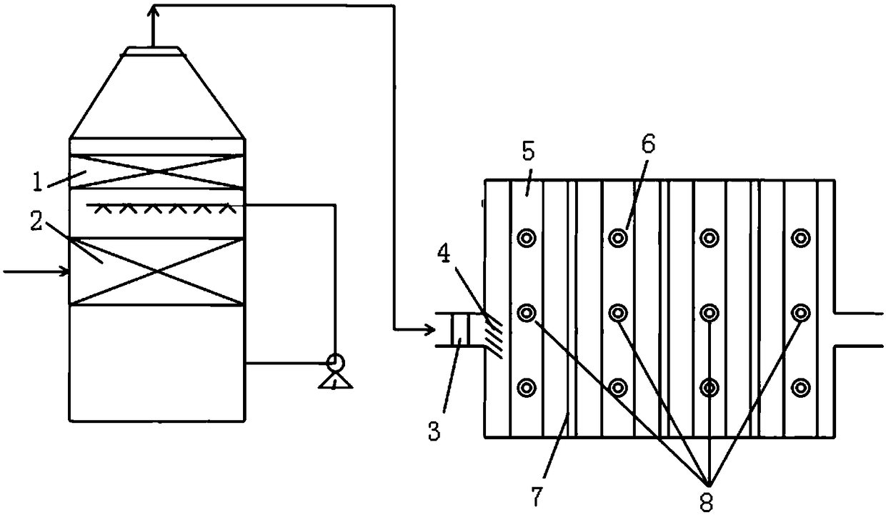
[0024] Such as figure 1 As shown, a device for removing VOC includes a connected spray system and a photocatalytic unit, the spray system is used to spray exhaust gas to remove dust in the exhaust gas; the photocatalytic unit includes a photocatalytic plate 7 and a light source, and the light source is arranged on It can be irradiated to the position of the photocatalytic plate 7, which is used to decompose VOC through photocatalysis; there is a humidity control device 3 connected between the spray system and the photocatalysis part, and the humidity control device 3 is used to control the exhaust gas filtered and dedusted from the spray system. The relative humidity is 30-50%.

[0025] The present invention finds that not only particles have a great influence on the photocatalytic process, but also humidity has a great influence on the photocatalytic process. On the one hand, moisture will increase the generation of hydroxyl radicals and superoxide radicals in the photocataly...


PUM


Abstract

The invention discloses equipment for removing VOC. The equipment for removing VOC comprises communicated spray system and photocatalysis part; the spray system is used for removing dust from waste air by performing spraying on the waste air; the photocatalysis part comprises photocatalysis plates and light source, wherein the light source is arranged at a position from where the photocatalysis plates can be irradiated, so that VOC can be decomposed by photocatalysis; and a humidity control device communicates between the spray system and the photocatalysis part so as to control relative humidity of the waste air, on which filtrating and dust-removing has been performed by the spray system, at 30-50%. By arranging the humidity control device, the equipment for removing VOC is capable of controlling relative humidity of dust-removed waste air at 30-50%, as well as effectively balancing catalytic activity and negative light-shielding effect of water vapor; and thus, the effect of improving photocatalytic reaction efficiency is achieved.

Description

technical field [0001] The invention relates to the field of environmental protection, in particular to a device and method for removing VOC. Background technique [0002] At present, there are various treatment technologies for industrial waste gas, such as activated carbon adsorption method, thermal oxidation method, photocatalytic oxidation method, low temperature plasma method, chemical reaction method, biological oxidation method, etc. Among them, the photocatalytic oxidation method has a small footprint and is easy to operate. Low cost, low design investment, no secondary pollution and become a green pioneer among various methods. The principle is to use a special high-energy ultraviolet beam to irradiate the odorous gas, change the molecular structure of the odorous gas, and make the molecular chain of the organic or inorganic high-molecular odor compound degrade and transform into a low-molecular compound under the irradiation of the high-energy ultraviolet beam, and...

Claims


Application Information

Patent Timeline
Patent Type & Authority Applications(China)
IPC IPC(8): B01D53/86B01D53/44B01D53/26
CPCB01D53/005B01D53/007B01D53/26B01D53/8687B01D2257/708B01D2259/804Y02A50/20
Inventor 兰勇李化王早军刘桢彭文茂
Owner 成都四维福腾环保设备有限公司
Why Eureka
Try Eureka