Automatic banding mechanism for flute tubes in bundles

A technology of sliding mechanism and pipe formation, which is applied in the direction of offensive equipment, pyrotechnics, weapon types, etc. It can solve the problems of automatic bandaging and inability to make elastic bands, and achieve the effect of uniform output speed and easy preliminary positioning

Active Publication Date: 2020-10-16
林德胜
View PDF5 Cites 0 Cited by
  • Summary
  • Abstract
  • Description
  • Claims
  • Application Information

AI Technical Summary

Problems solved by technology

[0004] The inventor previously applied for a patent (patent number; 2017104002048, the patent name is flute tube bundling machine), which realizes the positioning with the shaping mechanism through the swing of the binding mechanism and sets the elastic band on the shaping mechanism, and then works The personnel put the elastic band on the mechanical arm, spread the elastic band through the mechanical arm and put the elastic band on the molded flute tube. This method greatly improves the work efficiency, but the bundling of the flute tube At the same time, it is still necessary for the staff to quickly put the elastic on the mechanical arm, and it is impossible to automatically tie the elastic on a bundle of flute tubes. Now, the above patent is improved to automatically put the elastic on the shaping mechanism.

Method used


Image

  • Automatic banding mechanism for flute tubes in bundles
  • Automatic banding mechanism for flute tubes in bundles
  • Automatic banding mechanism for flute tubes in bundles

Examples


Embodiment Construction

[0021] Now in conjunction with accompanying drawing, the utility model is further elaborated.

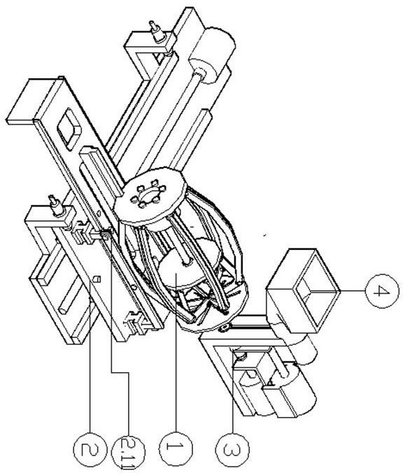
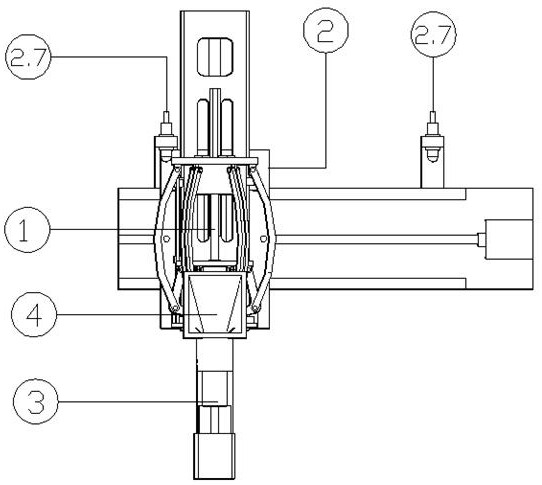
[0022] Such as figure 1 , 2 , 3, 4, 5, 6, and 7 show that the flute tubes are bundled into automatic banding mechanisms, including a banding mechanism 1, a sliding mechanism 2, an elastic band positioning upper sleeve mechanism 3 and an elastic band unloading mechanism 4, and bandage Mechanism 6 is opposite to the shaping mechanism. The ligation mechanism 1 includes a base 1.1, a guide plate 1.2, an elastic opening 1.3, a fixed plate 1.4, a telescopic mechanism 1.5, a push plate 1.6 and a moving plate 1.7, wherein the base 1.1 is fixed with a guide plate 1.2, and the guide plate 1.2 There are six guide holes 1.21 along the radial direction, and each guide hole 1.21 moves closer to and communicates with the center of the guide plate 1.2, and the guide plate 1.2 is also provided with an elastic opening 1.3, and the elastic opening 1.3 is evenly divided into six pieces And each guid...


PUM


Abstract

The invention discloses an automatic sleeve-binding mechanism for bundling whistling tubes. The automatic sleeve-binding mechanism comprises a sleeve-binding mechanism, a sliding mechanism, a rubber string positioning feeding mechanism and a rubber string discharging mechanism. The automatic sleeve-binding mechanism is characterized in that the sleeve-binding mechanism is fixed to the sliding mechanism, the rubber string positioning feeding mechanism is arranged on one side of the sliding mechanism, the rubber string discharging mechanism is arranged at the top of the rubber string positioningfeeding mechanism, wherein sleeve-binding mechanism slides on the sliding mechanism and is positioned with the rubber string positioning feeding mechanism. The arranging of the rubber string positioning feeding mechanism and the rubber string discharging mechanism can conveniently tidy rubber strings, and opening heads of the rubber strings are automatically sleeved with the rubber strings. The situation that the opening head of the rubber string cannot be sleeved with the rubber string on rubber string sleeve column sleeve due to the position can be prevented through a locating hole arrangedon the rubber string sleeve column and a locating pin arranged on the opening head of the rubber string. The output speed is uniform, the rubber string breakage caused by suddenly openings of the opening heads of the rubber strings are avoided, and primary positioning of the sleeve-binding mechanism is convenient to realize.

Description

technical field [0001] The invention relates to the field of fireworks and firecrackers manufacturing, in particular to an automatic banding mechanism for bundling flute tubes with rubber bands after bundling flute tubes automatically. Background technique [0002] The flute tubes in the fireworks barrel are one of the important components of fireworks. Before the production and assembly of fireworks, the flute tubes are usually bundled first, which facilitates the subsequent processing of the flute tubes. [0003] When bundling the flute tubes into bundles, the staff needs to arrange the flute tubes (that is, the flute tubes have pin holes at one end) and place them in the mold of the hexagonal frame, and then bundle them with rubber bands. After that, it develops to arrange the flute tube through the mechanical structure and place it in the mold. [0004] The inventor previously applied for a patent (patent number; 2017104002048, the patent name is flute tube bundling mac...

Claims


Application Information

Patent Timeline
Patent Type & Authority Patents(China)
IPC IPC(8): F42B4/30
CPCF42B4/30
Inventor 林德胜
Owner 林德胜
Why Eureka
Try Eureka