Optical lens system

An optical lens and lens technology, applied in the field of optical imaging, to achieve high imaging clarity, good thermal stability, and good imaging effects

Active Publication Date: 2018-11-30
JIANGXI LIANCHUANG ELECTRONICS CO LTD
View PDF6 Cites 20 Cited by
  • Summary
  • Abstract
  • Description
  • Claims
  • Application Information

AI Technical Summary

Problems solved by technology

[0004] However, among the existing technologies, none of the optical lenses currently on the market can well meet the above requirements. Therefore, it is urgent to develop a high-performance optical lens that can cooperate with unmanned driving.

Method used


Image

  • Optical lens system
  • Optical lens system
  • Optical lens system

Examples


Embodiment 1

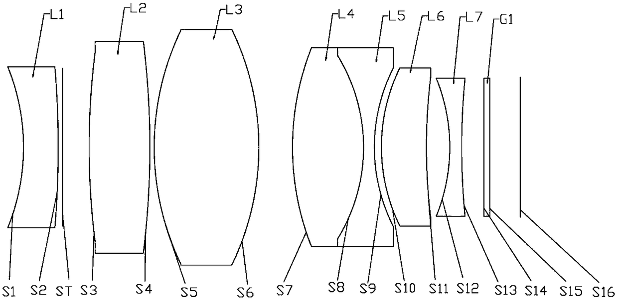
[0086] see Figure 1a , shows the structural diagram of the optical lens system in the first embodiment of the present invention, which includes in order from the object side to the imaging plane: the first lens L1 with negative power and the concave surface facing the object side; the stop ST; The second lens L2 with positive power and convex surface on both sides; the third lens L3 with positive power and convex surface toward the object side; the fourth lens L4 with positive power and convex surface on both sides; negative power and The fifth lens L5 whose both sides are concave, and the fourth lens L4 and the fifth lens L5 form a cemented lens; the sixth lens L6 with a positive refractive power and a convex surface facing the object side and a concave surface facing the image side; a negative refractive power and a seventh lens L7 with a concave surface facing the imaging surface; and a filter G1.

[0087] Wherein, the first lens L1 , the third lens L3 , the fourth lens L4...

Embodiment 2

[0132] see Figure 2a , shows the structural diagram of the optical lens system in the second embodiment of the present invention. The difference between the lens structure provided in this embodiment and the first embodiment is that: (1) the first lens L1 is a lens with concave surfaces on both sides , the third lens L3 is a lens with a convex surface on the object side and a concave surface on the image side, and the seventh lens L7 is a lens with a convex surface on the object side and a concave surface on the image side; (2) the stop ST is located between the second lens L2 and the third lens L3; (3 ) The second lens L2 is a glass spherical lens; (4) The relevant parameters of other lenses are different, and the specific relevant parameters of each lens are shown in Table 2-1.

[0133] table 2-1:

[0134]

[0135]

[0136] Please refer to Table 2-2, which shows the aspheric parameters of the seventh lens L7 in this embodiment.

[0137] Table 2-2:

[0138]

[01...

Embodiment 3

[0141] see Figure 3a , shows the structure diagram of the optical lens system in the third embodiment of the present invention. The lens structure provided by this embodiment is different from the first embodiment in that: (1) the first lens L1 is a lens with both sides concave , the third lens L3 is a lens with a convex surface on the object side and a concave surface on the image side, and the seventh lens L7 is a lens with a convex surface on the object side and a concave surface on the image side; (2) the stop ST is located between the second lens L2 and the third lens L3; (3 ) The second lens L2 is a glass spherical lens, and the sixth lens L6 is a glass aspheric lens; (4) The relevant parameters of other lenses are different, and the specific relevant parameters of each lens are shown in Table 3-1.

[0142] Table 3-1:

[0143]

[0144]

[0145] Please refer to Table 3-2, which shows the aspheric parameters of the sixth lens L6 and the seventh lens L7 in this embo...


PUM


Abstract

The invention provides an optical lens system, the optical lens system sequentially comprises, from the object side to an imaging surface, a first lens, a second lens, a third lens, a fourth lens, a fifth lens, a sixth lens and a seventh lens, wherein the first lens is provided with negative focal power, and the concave surface of the first lens faces the object side; the second lens is provided with positive focal power, and both sides of the second lens are of convex surfaces; the third lens is provided with positive focal power, and the convex surface of the third lens faces the object side; the fourth lens is provided with positive focal power, and both sides of the fourth lens are of convex surfaces; the fifth lens provided with negative focal power, the both sides of the fifth lens are of concave surfaces, and the fourth lens and the fifth lens constitute a agglutinate ophthalmic lens; the sixth lens is provided with positive focal power, the concave surface of the sixth lens faces the object side, and the concave surface of the sixth lens faces the image side; and the seventh lens is provided with negative focal power, and the concave surface of the seventh lens faces the imaging surface. Diaphragm is arranged between the first lens and the third lens, the first lens, a fourth lens and the fifth lens are of glass spherical lenses, and the seventh lens is of a glass aspheric lens. A camera lens of the optical lens system has heat stability, has sky-high resolving power to objects transmitting or reflecting monochromatic light with different wave lengths, and can meetthe unmanned camera lens requirements.

Description

technical field [0001] The invention relates to the technical field of optical imaging, in particular to an optical lens system. Background technique [0002] In recent years, with the promotion of the concept of unmanned driving and the continuous maturity of unmanned driving technology, unmanned driving may become a trend in the development of automobiles in the future. The key to unmanned driving technology lies in how to obtain sufficiently accurate road information, so unmanned driving has unique requirements for each component of the car. [0003] Among them, the on-board camera lens is a key component of unmanned driving, which acts as the eyes of unmanned driving, and its performance directly affects the safety factor of unmanned driving. Unmanned driving requires the front port diameter of the lens to be as small as possible, with strong light transmission ability, and can adapt to the change of light and shade in the external environment. The thermal stability of...

Claims


Application Information

Patent Timeline
Patent Type & Authority Applications(China)
IPC IPC(8): G02B13/00G02B13/18
CPCG02B13/0005G02B13/0045G02B13/006G02B13/18G02B9/64G02B9/60G02B9/62H04N23/57
Inventor 魏文哲鲍宇旻陈伟建刘绪明曾吉勇王克民
Owner JIANGXI LIANCHUANG ELECTRONICS CO LTD
Why Eureka
Try Eureka