
Optical module and optical network system

A technology of optical module and control module, applied in the field of optical communication, can solve problems such as communication failure and affecting IIC bus level

Active Publication Date: 2018-12-04
HISENSE BROADBAND MULTIMEDIA TECH
View PDF5 Cites 5 Cited by
  • Summary
  • Abstract
  • Description
  • Claims
  • Application Information

AI Technical Summary

Problems solved by technology

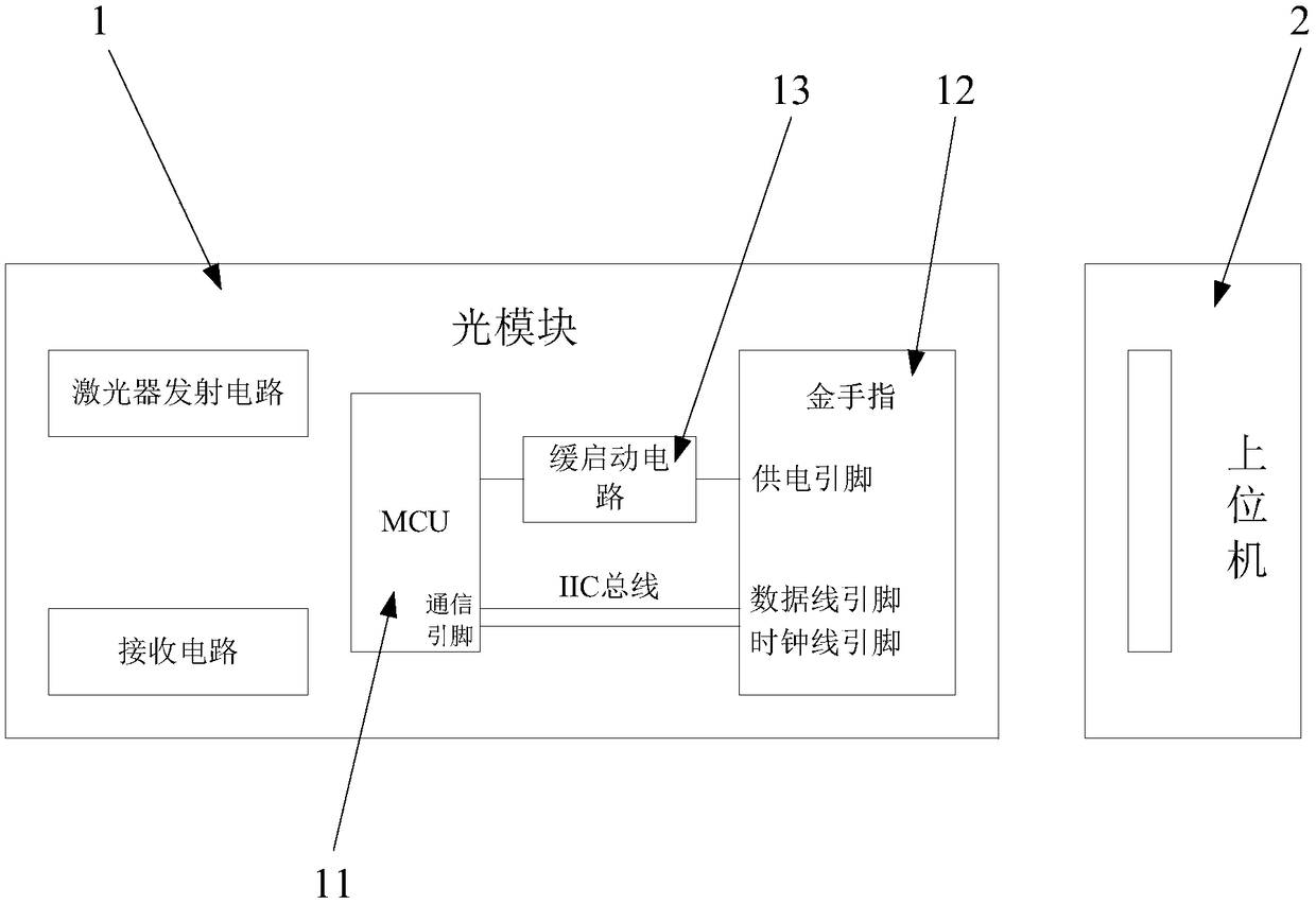
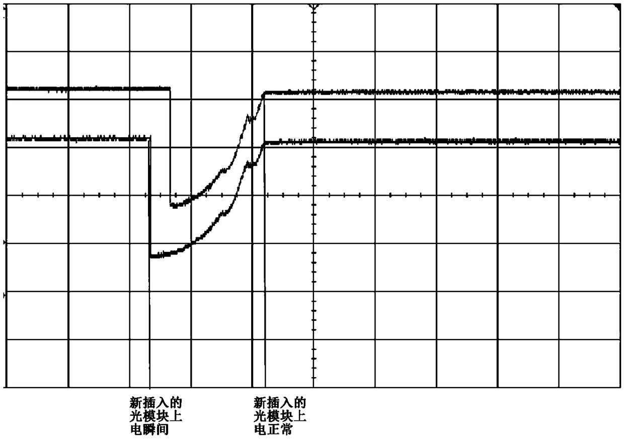
[0005] This application provides an optical module and an optical network system to solve the current technical problem that the level of the IIC bus is affected when the optical module is inserted into the host computer, which may easily cause communication failure

Method used


Image

  • Optical module and optical network system
  • Optical module and optical network system
  • Optical module and optical network system

Examples


Embodiment Construction

[0021] In order to enable those skilled in the art to better understand the technical solutions in the present application, the technical solutions in the embodiments of the present application will be clearly and completely described below in conjunction with the drawings in the embodiments of the present application. Obviously, the described The embodiments are only some of the embodiments of the present application, not all of them. Based on the embodiments in this application, all other embodiments obtained by persons of ordinary skill in the art without creative efforts shall fall within the scope of protection of this application.

[0022] In modern optical networks, as the requirements for bandwidth become higher and higher, the demand for optical modules is increasing. There are ten or twenty optical modules on a host computer. Most of these modules are thermal Insert and remove the optical module. According to the design requirements of the optical module, the upper ...


PUM


Abstract

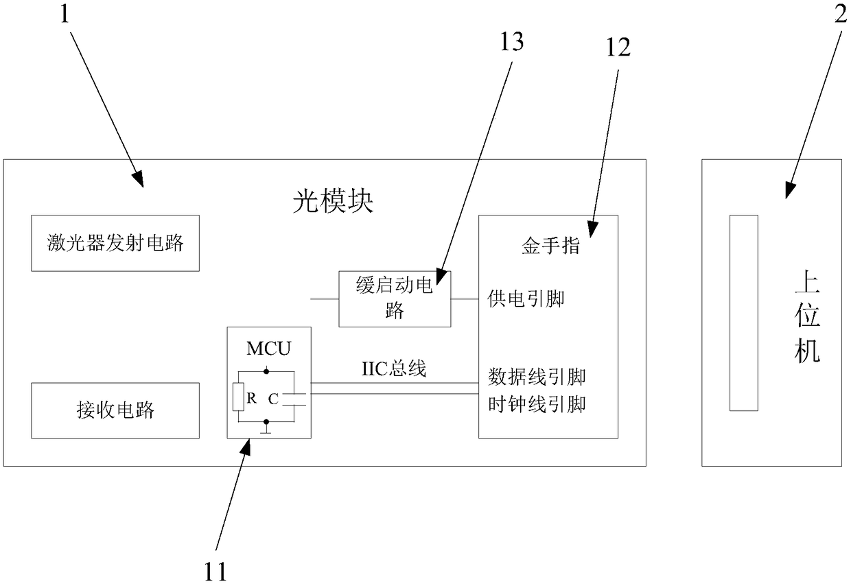
The present application discloses an optical module and an optical network system. The optical module includes an MCU and a golden finger. The MCU is provided with two communication pins. The golden finger is provided with a data line pin and a clock line pin. One communication pin of the MCU is connected to the data line pin through a data line. The other communication pin of the MCU is connectedto the clock line pin through a clock line. The data line and the clock line are provided with switches. The MCU controls the on-off state of the golden finger by the switches. According to the optical module provided by the present application, the switches are disposed on the data line and the clock line connecting the MCU and the golden finger of the optical module. When the MCU is powered on,the MCU turns off the switches and the power supply pin of the optical module cannot supply power to the MCU via an IIC bus such that the level of the IIC bus cannot be affected, that the communication between the IIC bus and the operating optical module cannot be affected, and that the normal communication of the optical module is ensured.

Description

technical field [0001] The present application relates to the technical field of optical communication, in particular to an optical module and an optical network system. Background technique [0002] The optical fiber communication method uses light waves as the information carrier and optical fiber as the transmission medium. The optical module is a very important optical signal interface device in optical fiber communication. One end of the optical module is connected to the optical fiber as an optical interface, and the other end is used as The electrical interface is connected to external communication equipment, and the optical module can convert optical signals and electrical signals. [0003] As the bandwidth requirements are getting higher and higher, the demand for optical modules in optical networks is increasing. There are often ten or twenty optical modules on a host computer. Most of these optical modules are hot-swappable optical modules. module. In the prior...

Claims


Application Information

Patent Timeline
IPC IPC(8): H04B10/27H04B10/40
CPCH04B10/27H04B10/40
Inventor 李绍波
Owner HISENSE BROADBAND MULTIMEDIA TECH
Learn More