Large-diameter pipeline welding device

A welding device and large-diameter technology, which is applied in the direction of welding equipment, auxiliary equipment, auxiliary welding equipment, etc., can solve the problems of damage to the level of splicing, damage of solder joints or pre-welding, and short welding time

Active Publication Date: 2022-07-29
中交三航(南通)海洋工程有限公司
View PDF14 Cites 3 Cited by
  • Summary
  • Abstract
  • Description
  • Claims
  • Application Information

AI Technical Summary

Problems solved by technology

[0005] During the welding process, protecting the welding points with inert gas can indeed ensure the welding quality, but when welding two pipes, it is necessary to splice the two pipes to ensure that the joints of the two pipes are at the same level. After welding, the pipe after splicing is often unable to move before the welding is completed, otherwise the level of the splicing will be damaged. For small diameter pipes, the required welding time is shorter, and the diameter of the pipe is small, often at the point After the welding or pre-welding is completed, the pipe can be moved, but for large-diameter pipes, the welding time is longer. At the same time, due to the diameter and weight, once the welding starts, the movement of the pipe will lead to welding spots or pre-welding. It is often impossible to move the pipe before the welding is completed by means of spot welding or pre-welding, so the welding of large-diameter pipes has great limitations in this respect

Method used


Image

  • Large-diameter pipeline welding device
  • Large-diameter pipeline welding device
  • Large-diameter pipeline welding device

Examples


Embodiment 1

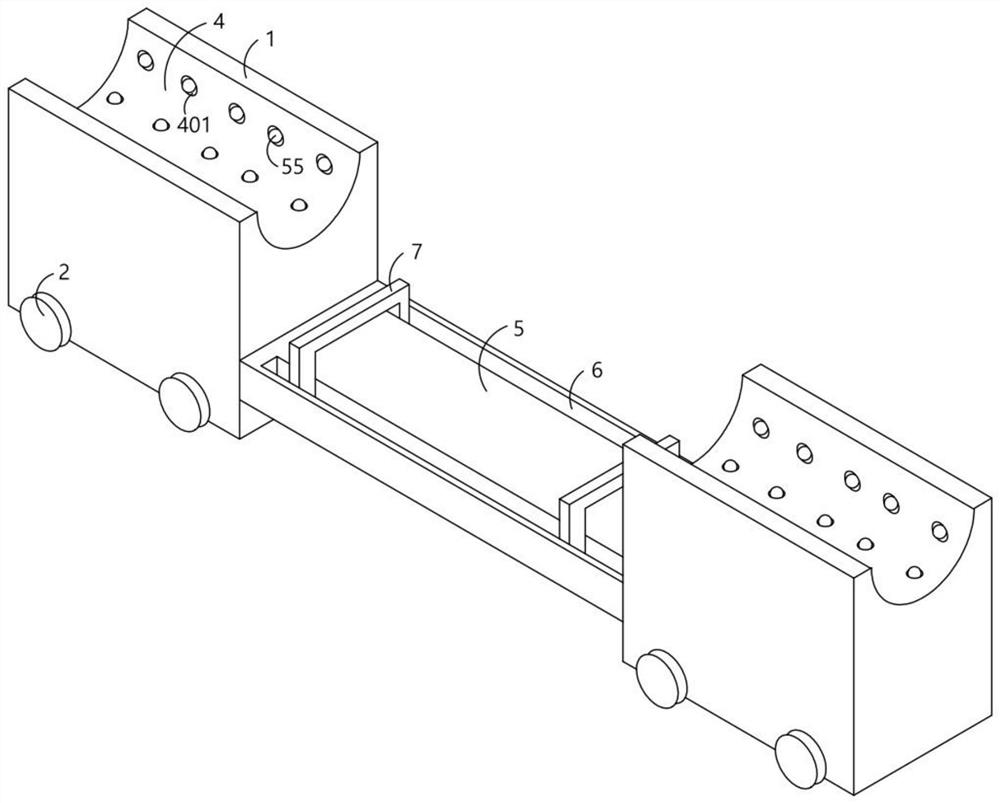
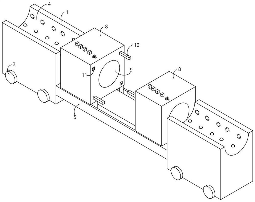
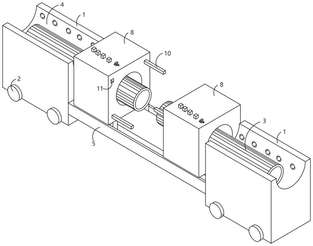
[0039] A large-diameter pipeline welding device, comprising two placing tables 1, the placing table 1 is used for placing the pipeline 3, the two placing tables 1 in this embodiment are arranged at intervals, and the side of the placing table 1 is provided with a moving wheel 2, The moving wheel 2 is a roller. In order to facilitate the subsequent movement of the placing table 1, the placing table 1 is provided with a placing slot 4 for placing the pipeline 3. The two placing platforms 1 are provided with a placing slot 4. The placing table 1 is on the same horizontal plane, and the placing groove 4 is set in an arc shape. At this time, when the pipes 3 are placed inside the placing groove 4, under the action of gravity, the lower parts of the two pipes 3 will be in the lowest section of the placing groove 4. At this time, the centers of the two pipes 3 are naturally on the same horizontal plane, and a track plate 5 is fixedly arranged between the two placing tables 1. The trac...

Embodiment 2

[0043] The fixed box 8 is provided with an inflatable block 19 that communicates with the inflator 18. The inflatable block 19 communicates with the airbag 17 and the inflation of the inflator 18 at the same time. The inflatable block 19 has a certain elasticity and can be made of elastic materials such as rubber. Inflatable objects, a one-way valve 20 and a pressure regulating valve 21 are provided at the connection between the inflator 18 and the inflatable block 19. The one-way valve 20 ensures that the gas can only enter the inflatable block 19 from the inflator 18. The pressure regulating valve 21 is The electric throttle valve model JL923W produced by Gongheng Valve Co., Ltd. can adjust the pressure regulating valve 21 to make the inflation speed into the inflatable block 19. The model of the pressure regulating valve 21 is not unique, as long as it can be used as an inflator 18 When inflating the airbag 17 and the inflatable block 19 at the same time, the air intake spee...

Embodiment 3

[0045] On the basis of the first embodiment, the structure of the control assembly in the first embodiment is disclosed. The control assembly includes a control cavity 25 opened inside the fixed box 8 , and a second electrical connection with the inflator 18 is arranged inside the control cavity 25 . The switch 26, the control cavity 25 is provided with a control rod 27 which is in active contact with the second switch 26. The control rod 27 and the second switch 26 cooperate to control the inflator 18. When the control rod 27 squeezes the second switch 26, the gas is inflated at this time. The machine 18 starts to work. On the contrary, when the control rod 27 is separated from the second switch 26, the inflator 18 stops working. One end of the control rod 27 can move out of the control cavity 25 and is blocked by the limit rod 28. The control rod 27 is fixed. A strut 271 that is in active contact with the inflatable block 19 is connected. The control rod 27 is provided with a...


PUM


Abstract

The invention provides a large-diameter pipeline welding device which comprises two placing tables, each placing table is provided with a placing groove used for placing a pipeline, a track plate is fixedly arranged between the placing tables, two telescopic track rods are movably arranged on the surface of the track plate, and the telescopic track rods are fixedly connected with a fixing box. A through hole allowing a pipeline to movably penetrate through is formed in the fixing box, the fixing box is fixedly connected with a plurality of inserting rods, inserting grooves allowing the inserting rods to be movably inserted are formed in one side of the fixing box, and a fixing plate used for fixing the pipeline and an air bag are arranged in the through hole. In the using process, a pipeline is firstly placed in a containing groove, a welded part of the pipeline is washed and dried, the center of the pipeline and the center of a through hole are located on the same horizontal plane by adjusting a telescopic rail rod, then the pipeline is fixed through a fixing plate and an air bag, and the two fixing boxes are fixed through inserting rods and buckle assemblies; and the pipeline can be moved at will during welding.

Description

technical field [0001] The invention relates to the technical field of pipeline welding, in particular to a large-diameter pipeline welding device. Background technique [0002] Welding technology is mostly used for the connection between metal materials. The welding quality directly determines the strength of the material or part after welding. Welding connection between two materials, among which the welding connection between pipes has high requirements on the quality of welding, and the welding connection between pipes is also very difficult, especially the welding connection between large-diameter pipes, which requires very high welding technology. high. [0003] A large-diameter pipeline welding device (main classification number is B23K37 / 00) provided by the publication number "CN201210191677.9" includes a pipeline support tool, and the pipeline support tool includes a horizontally arranged pipeline support cantilever, which is arranged on the pipeline support cantil...

Claims


Application Information

Patent Timeline
Patent Type & Authority Applications(China)
IPC IPC(8): B23K37/00B23K37/04B23K101/06
CPCB23K37/00B23K37/0443B23K2101/06
Inventor 汪峥王圣鉴赵铁军徐汝绎顾笑僮
Owner 中交三航(南通)海洋工程有限公司
Why Eureka
Try Eureka