A Retrofitting Method to Solve the Too Tight Welding of Z-bend Welding Machine

A welding machine and over-tightening technology, applied in the field of welding, can solve the problems of material fatigue and poor toughness, and achieve the effects of small radiation surface, stable cooling effect and low transformation cost

Active Publication Date: 2021-07-13
HENGSHUI YINGLI NEW ENERGY
View PDF0 Cites 0 Cited by
  • Summary
  • Abstract
  • Description
  • Claims
  • Application Information

AI Technical Summary

Problems solved by technology

[0004] Since the current ribbons are all impregnated with flux, and the welding temperature and environment of the Z-bend welding are the same as those of other parts of the cell, the soldering is tight. During the transmission process of the battery string, the edge of the cell is closely welded to the ribbon. Poor toughness, easy to cause cracks due to problems such as material fatigue, and this problem is technological and cannot be effectively avoided. Therefore, the present invention proposes a transformation method to solve the problem of excessively tight Z-bend welding of the welding machine to solve the problems in the prior art. inadequacies of

Method used


Image

  • A Retrofitting Method to Solve the Too Tight Welding of Z-bend Welding Machine
  • A Retrofitting Method to Solve the Too Tight Welding of Z-bend Welding Machine

Examples


Embodiment 1

[0020] according to figure 2 As shown, this embodiment proposes a transformation method to solve the excessively tight Z-bend welding of the welding machine, including the following steps:

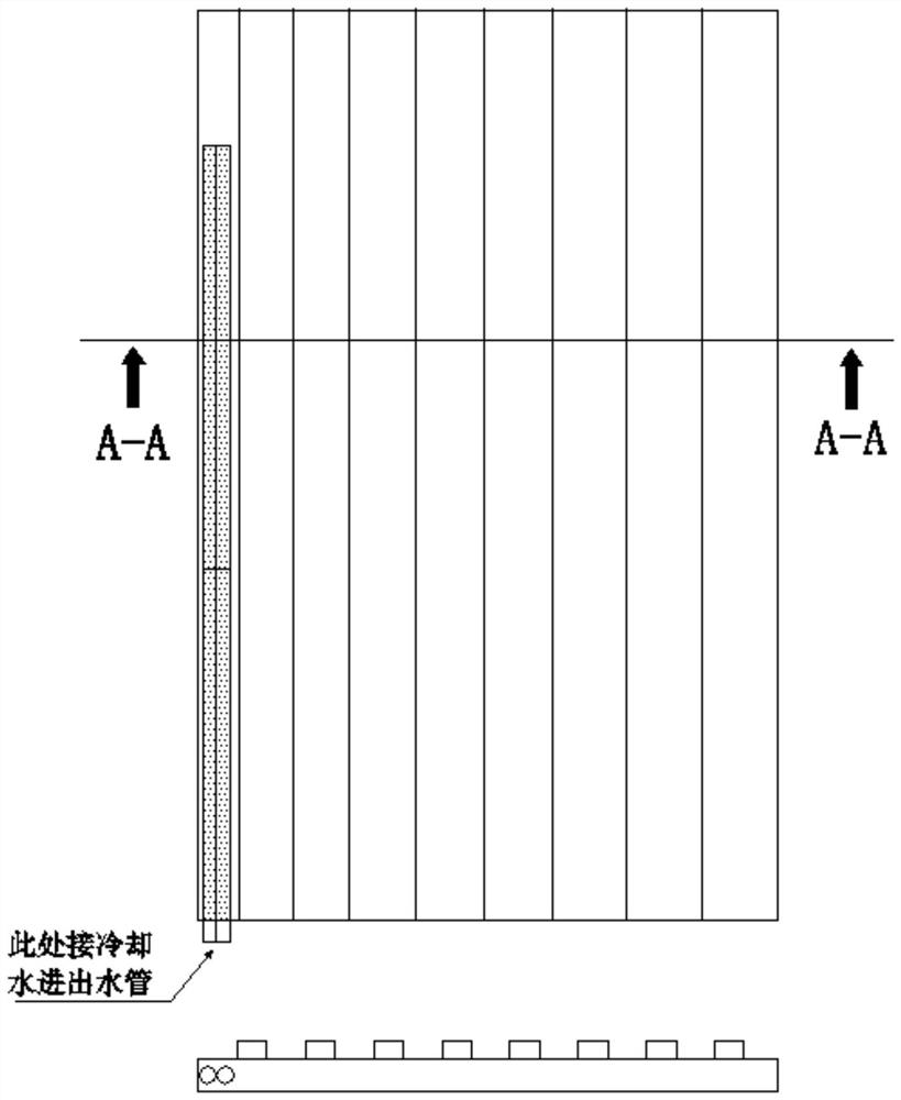
[0021] Step 1: Design a thin-walled copper tube of Φ4mm*560mm. The thin-walled copper tube is cast from red copper. Finally, the thin-walled copper tube is folded in half by intermediate heating to form a U-shaped thin-walled copper tube. U-shaped thin-walled copper tube The inner wall of the tube is a straight wall structure, and the wall thickness of the U-shaped thin-walled copper tube is 0.4mm;

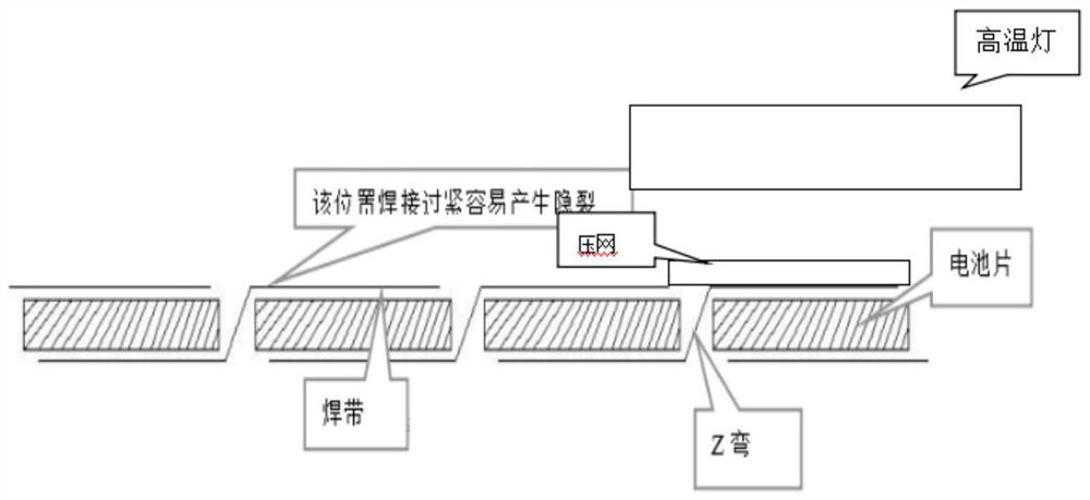
[0022] Step 2: Transform the press net, install U-shaped thin-walled copper tubes on the upper left side of the press net, ensure that the U-shaped thin-walled copper tubes are located between the press net and the high-temperature lamp, and control the impact of the U-shaped thin-walled copper tubes on the battery An 8mm wide area is blocked where the edge of the sheet is connected to the r...

Embodiment 2

[0026] according to figure 2 As shown, this embodiment proposes a transformation method to solve the excessively tight Z-bend welding of the welding machine, including the following steps:

[0027] Step 1: Design a thin-walled copper tube of Φ4mm*560mm. The thin-walled copper tube is cast from red copper. Finally, the thin-walled copper tube is folded in half by intermediate heating to form a U-shaped thin-walled copper tube. U-shaped thin-walled copper tube The inner wall of the tube is a straight wall structure, and the wall thickness of the U-shaped thin-walled copper tube is 0.4mm;

[0028] Step 2: Transform the press net, install U-shaped thin-walled copper tubes on the upper left side of the press net, ensure that the U-shaped thin-walled copper tubes are located between the press net and the high-temperature lamp, and control the impact of the U-shaped thin-walled copper tubes on the battery An 8mm wide area is blocked where the edge of the sheet is connected to the r...


PUM

PropertyMeasurementUnit
thicknessaaaaaaaaaa

Abstract

The invention discloses a transformation method for solving the problem of excessive Z-bend welding of a welding machine. Wall copper tube, control the U-shaped thin-walled copper tube to produce an 8mm wide area to be blocked at the position where the edge of the battery sheet is connected to the welding strip; weld the copper sheet on the side of the U-shaped thin-walled copper tube; use the hose to connect the U-shaped thin-walled copper tube The inner cavity of the wall copper tube is separately connected with the water inlet and the water outlet of the external cooling system; the present invention adds U-shaped thin-walled copper tubes to the pressure net, and the U-shaped thin-walled copper tubes only affect the welding of the Z bend and the edge of the battery sheet The effect does not affect the welding quality of other parts, and the method of the present invention only modifies the pressing net, which has the advantages of simplicity, quickness, and low cost of modification. The cooling effect of using U-shaped thin-walled copper tubes is stable, with concentrated effect and small radiation surface significant effect.

Description

technical field [0001] The invention relates to the field of welding technology, in particular to a transformation method for solving the problem of excessive Z-bend welding of a welding machine. Background technique [0002] In the welding process of the existing photovoltaic cells, the soldering strips are impregnated with flux through the root, and the cells are gradually warmed up, and under the high temperature irradiation of the welding lamp, the soldering strips are welded with the main grid lines of the cells to form a string, and the battery string is welded. After that, it is placed on the tempered glass with EVA film according to the process requirements, and the components are connected through the confluence belt. After laying the second layer of EVA film and the back plate, they flow through the transmission line and enter the next lamination process for packaging. There is a Z bend in the ribbon between the two cells. Once the solder ribbon is too tightly weld...

Claims


Application Information

Patent Timeline
Patent Type & Authority Patents(China)
IPC IPC(8): B23P15/00
CPCB23P15/00
Inventor 于智涛王志超李立阳王铁冬邢晓臣陈俊玉张磊
Owner HENGSHUI YINGLI NEW ENERGY
Why Eureka
Try Eureka