Nursing bed for paralyzed patient

A technology for paralyzed patients and nursing beds, applied in the field of nursing beds, can solve the problems of inconvenient handling, troublesome urination and defecation of paralyzed patients, and achieve the effects of convenient handling, excretion, and urination and defecation.

Pending Publication Date: 2018-12-07
梁馨文
View PDF24 Cites 4 Cited by
  • Summary
  • Abstract
  • Description
  • Claims
  • Application Information

AI Technical Summary

Problems solved by technology

[0005] In order to overcome the disadvantages of troublesome defecation and inconvenient disposal of excreta in the prior art, the technica...

Method used


Image

  • Nursing bed for paralyzed patient
  • Nursing bed for paralyzed patient
  • Nursing bed for paralyzed patient

Examples


Embodiment 1

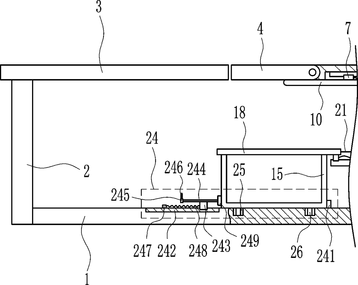
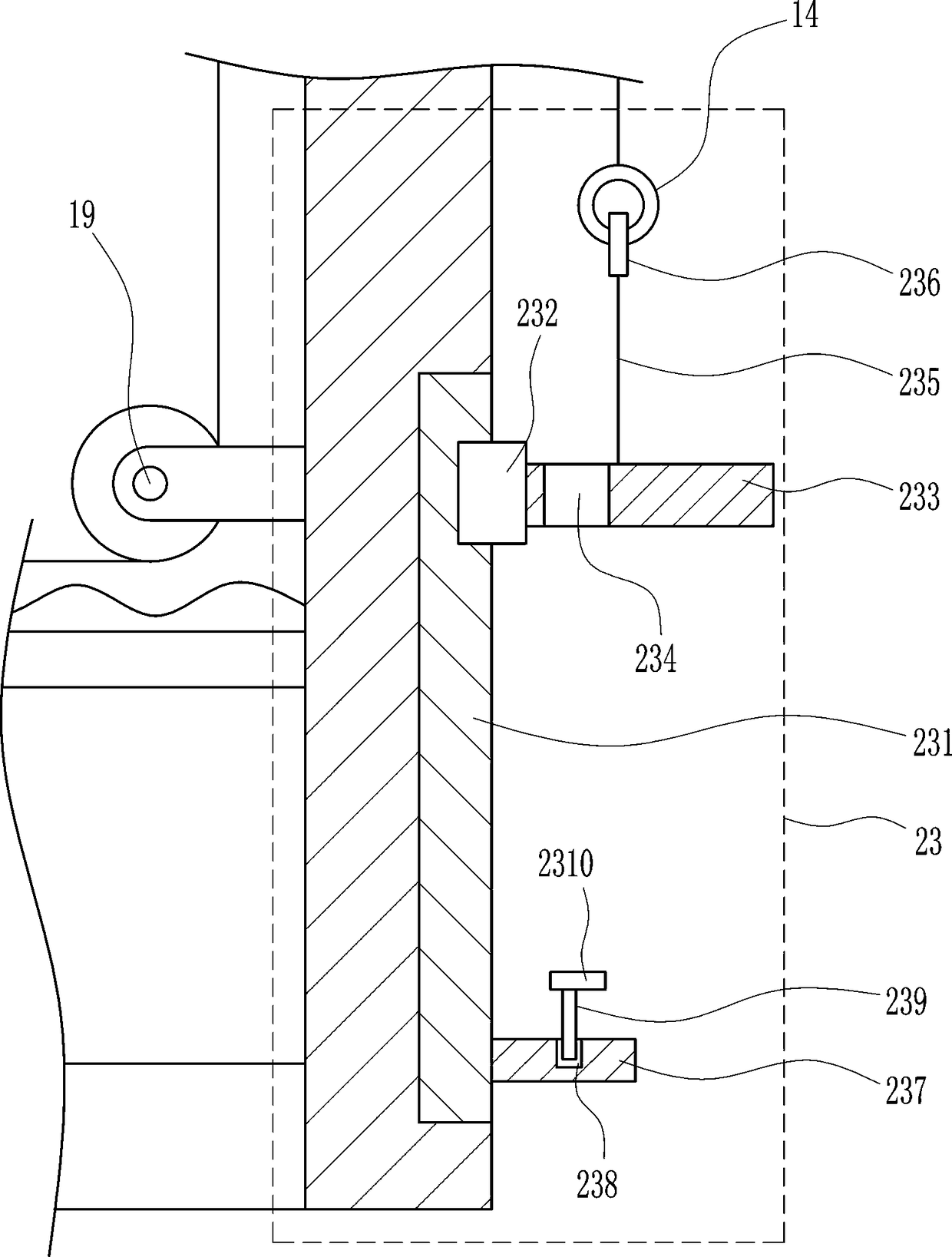
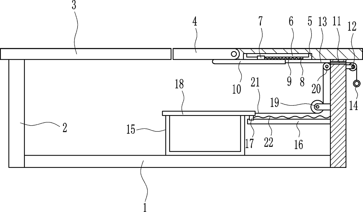
[0025] A nursing bed for paralyzed patients, such as Figure 1-5 As shown, it includes a bottom plate 1, a support plate 2, a placement plate 3, a rotating plate 4, a first slide rail 6, a first slider 7, a first connecting block 8, a first spring 9, a baffle plate 10, a first fixed Pulley 12, first stay wire 13, draw ring 14, frame body 15, second slide rail 16, second slide block 17, cover plate 18, the second fixed pulley 19, the third fixed pulley 20, the second stay wire 21 and the first Two springs 22, the left and right sides of the bottom plate 1 are connected with support plates 2, the tops of the support plates 2 on the left and right sides are connected with the placement plate 3, the left side of the right side placement plate 3 is hinged with a rotating plate 4, and the left side of the right side placement plate 3 is left There is an installation groove 5 on the side, and a first slide rail 6 is arranged in the installation groove 5, a first slider 7 is slidably ...

Embodiment 2

[0027] A nursing bed for paralyzed patients, such as Figure 1-5 As shown, it includes a bottom plate 1, a support plate 2, a placement plate 3, a rotating plate 4, a first slide rail 6, a first slider 7, a first connecting block 8, a first spring 9, a baffle plate 10, a first fixed Pulley 12, first stay wire 13, draw ring 14, frame body 15, second slide rail 16, second slide block 17, cover plate 18, the second fixed pulley 19, the third fixed pulley 20, the second stay wire 21 and the first Two springs 22, the left and right sides of the bottom plate 1 are connected with support plates 2, the tops of the support plates 2 on the left and right sides are connected with the placement plate 3, the left side of the right side placement plate 3 is hinged with a rotating plate 4, and the left side of the right side placement plate 3 is left There is an installation groove 5 on the side, and a first slide rail 6 is arranged in the installation groove 5, a first slider 7 is slidably ...

Embodiment 3

[0030] A nursing bed for paralyzed patients, such as Figure 1-5 As shown, it includes a bottom plate 1, a support plate 2, a placement plate 3, a rotating plate 4, a first slide rail 6, a first slider 7, a first connecting block 8, a first spring 9, a baffle plate 10, a first fixed Pulley 12, first stay wire 13, draw ring 14, frame body 15, second slide rail 16, second slide block 17, cover plate 18, the second fixed pulley 19, the third fixed pulley 20, the second stay wire 21 and the first Two springs 22, the left and right sides of the bottom plate 1 are connected with support plates 2, the tops of the support plates 2 on the left and right sides are connected with the placement plate 3, the left side of the right side placement plate 3 is hinged with a rotating plate 4, and the left side of the right side placement plate 3 is left There is an installation groove 5 on the side, and a first slide rail 6 is arranged in the installation groove 5, a first slider 7 is slidably ...


PUM


Abstract

The invention relates to a nursing bed, in particular to a nursing bed for a paralyzed patient. The nursing bed for the paralyzed patient aims at achieving the technical purposes of making it convenient for the paralyzed patient to defecate and making it convenient to dispose excreta. According to the technical scheme, the nursing bed for the paralyzed patient comprises a bottom plate, supportingplates, placement plates, a rotary plate, a first sliding rail, a first sliding block, a first connecting block, a first spring, a baffle, a first fixed pulley, a first pull line and the like; the supporting plates are connected to the left and right sides of the bottom plate, the placement plates are connected to the top ends of the supporting plates on the left and right sides, the rotary plateis hinged to the left side of the placement plate on the right side, a mounting groove is formed in the left side of the bottom of the placement plate on the right side, and the first sliding rail isarranged in the mounting groove. The nursing bed for the paralyzed patient achieves the effects of making it convenient for the paralyzed patient to defecate and making it convenient to dispose excreta; by the arrangement of the rotary plate, the paralyzed patient can defecate conveniently, and by the arrangement of wheel grooves and wheels, a nursing worker can dispose excreta of the paralyzed patient more conveniently.

Description

technical field [0001] The invention relates to a nursing bed, in particular to a nursing bed for paralyzed patients. Background technique [0002] Medical devices refer to instruments, equipment, utensils, in vitro diagnostic reagents and calibrators, materials, and other similar or related items that are directly or indirectly used on the human body, including required computer software; their effects are mainly obtained through physical means, not Obtained by pharmacological, immunological or metabolic means, or with the participation of these means but only as an auxiliary function; its purpose is the diagnosis, prevention, monitoring, treatment or alleviation of disease; the diagnosis, monitoring, treatment, alleviation or function of injury Compensation; examination, replacement, regulation or support of physiological structures or processes; life support or maintenance; pregnancy control; providing information for medical or diagnostic purposes by examining samples fr...

Claims


Application Information

Patent Timeline
IPC IPC(8): A61G7/02A61G7/05
CPCA61G7/02A61G7/0503
Inventor 梁馨文
Owner 梁馨文
Why Eureka
Try Eureka